Code Monkey home page Code Monkey logo

madgwickahrs's Introduction

Madgwick Library

Check Arduino status Compile Examples status Spell Check status

This library wraps the official implementation of MadgwickAHRS algorithm to get orientation of an object based on accelerometer and gyroscope readings

License

Copyright (c) Arduino LLC. All right reserved.

This library is free software; you can redistribute it and/or modify it under the terms of the GNU Lesser General Public License as published by the Free Software Foundation; either version 2.1 of the License, or (at your option) any later version.

This library is distributed in the hope that it will be useful, but WITHOUT ANY WARRANTY; without even the implied warranty of MERCHANTABILITY or FITNESS FOR A PARTICULAR PURPOSE. See the GNU Lesser General Public License for more details.

You should have received a copy of the GNU Lesser General Public License along with this library; if not, write to the Free Software Foundation, Inc., 51 Franklin St, Fifth Floor, Boston, MA 02110-1301 USA

Implementation of Madgwick’s IMU and AHRS algorithms. See: http://www.x-io.co.uk/node/8#open_source_ahrs_and_imu_algorithms

madgwickahrs's People

Contributors

aentinger avatar agdl avatar dependabot[bot] avatar fede85 avatar hbisby avatar mbanzi avatar monolith-jaehoon avatar paulstoffregen avatar per1234 avatar

Stargazers

 avatar  avatar  avatar  avatar  avatar  avatar  avatar  avatar  avatar  avatar  avatar  avatar  avatar  avatar  avatar  avatar  avatar  avatar  avatar  avatar  avatar  avatar  avatar  avatar  avatar  avatar  avatar  avatar  avatar  avatar  avatar  avatar  avatar  avatar  avatar  avatar  avatar  avatar  avatar  avatar  avatar  avatar  avatar  avatar  avatar  avatar  avatar  avatar  avatar  avatar  avatar  avatar  avatar  avatar  avatar  avatar  avatar  avatar  avatar  avatar  avatar  avatar  avatar  avatar  avatar  avatar  avatar  avatar  avatar  avatar  avatar  avatar  avatar  avatar  avatar  avatar  avatar  avatar  avatar  avatar  avatar  avatar  avatar  avatar  avatar  avatar  avatar  avatar  avatar  avatar  avatar  avatar  avatar  avatar  avatar  avatar  avatar  avatar  avatar  avatar

Watchers

 avatar  avatar  avatar  avatar  avatar  avatar  avatar  avatar  avatar  avatar  avatar  avatar  avatar  avatar  avatar  avatar  avatar  avatar  avatar  avatar  avatar  avatar  avatar  avatar  avatar  avatar  avatar  avatar  avatar  avatar  avatar  avatar  avatar  avatar  avatar  avatar  avatar  avatar  avatar  avatar  avatar  avatar  avatar

madgwickahrs's Issues

Madgwick::computeAngles incorrect.

The yaw pitch and roll values returned by computeAngles is incorrect.
for example, using q = [0.5000 0 0.7071 -0.5000], the compute angles would return yaw: -90, pitch: 45, roll: -90 when the correct values are yaw: 90, pitch: 45, roll: -90. This problem only arises in certain quadrants.
It is a little hard to visualize these rotations, but I trust the implementation here: https://quaternions.online/
it is my go-to comparison for testing.
A correct implementation can be found on the wikipedia page for this conversion (https://en.wikipedia.org/wiki/Conversion_between_quaternions_and_Euler_angles)

Centrifugal Force Compensation IMU

I am developing a prototype attitude indicator.
I use a board LSM6DS3 as accel + gyro sensors + STM32 as microcontroller for mathematics and ESP32 for graphics generation.
I do not enter the values of the magnetometer axes, and according to the library code

if((mx == 0.0f) && (my == 0.0f) && (mz == 0.0f)) {

in the case of mx = 0, my = 0, mz = 0 the filter will only take the value of accelerations and angular velocities of the gyroscope.
On the ground this filter works great.
photo1692643955 (2)
https://disk.yandex.ru/i/vr-5XOem67E0WQ
But in flight it behaves like a glass of water - i.e. useless.
left_turn
https://disk.yandex.ru/i/w4hdS5hw0NJngw
What is being measured is not gravity, but centripetal acceleration.
Accordingly, you need to compensate for this somehow.
I found only theoretical materials, but no one implemented it in code, except perhaps iNavFlight.
What do these coefficients give?

#define sampleFreqDef   512.0f          // sample frequency in Hz
#define betaDef         0.1f            // 2 * proportional gain

#define sampleFreqDef 512.0f // sample frequency in Hz

My knowledge of programming is not very good, and I cannot implement any ideas in the program, although there are many different options for solving the problem.
As far as I understand this process - it is necessary, at the beginning of a right or left roll, to give priority to the data from the gyroscope, and “mute” the accelerometer data, when the turn ends, the data from the accelerometer again takes priority over the angular velocity data from the gyroscope.
Can anyone explain whether it is possible to implement compensation for centrifuge forces in MadgwickAHRS or is this filter not capable of working in flight?
I found and use a more “advanced” filter, which adds the magnetometer signal.
I haven't tested it in flight yet.
I wanted to refine and test the
MadgwickAHRS filter.
After all, even filtering only using an accelerometer and magnetometer gives the roll, pitch and yaw angles.

Yaw drift LSM6D3S

Hi,

  1. I see Yaw drift with the example code. using LSM6D3S with Arduino cc.
  2. I looked at various forums and see that 9DoF using Magnetometer is used to compensate gyro.
  3. without magnetometer, the drift could be compensated by few methods. Is this already part of this library [i could not find such code]
  4. and if not, is there any reason why it is not yet taken up?

Thanks

Errors calculating angles and wrong angles

Hello!

Whenever I use the code you provided, I get the following two errors:

  • When using randomly chosen Quaternions, the filter won't be able to calculate the expected euler angles and give me the error that the argument in a trigonometric function (sin, cos etc.) is wrong.

  • When the filter runs without an error, the euler angles I read with the getRoll etc. methods are completely wrong and when I rotate my sensor 360° around one axis, the corresponding euler angle changes only in around 50-60°

I update the filter with a frequency of 512 Hz, changed my beta to values between 1 and 0.1 and the gyroscope values are in degrees per second. Do you know a solution or what possibly might be my problem?

Kind Regards,
Robert

Madgwick Implementation

Hi all

I have been using these filters for the last couple of years and there are a couple of things that I am confused about with Curie implementation.

You have the sample frequency set to 512hz but all the implementations that I have seen and what I use is that the sample frequency is calculated with the main (sketch) and passed to the filter. The second is that I would recommend that betaDef be set within the sketch to allow the user to tune the filter.

The last is that there is an error in the source code that is on Seb Madwick website in the "c" file. Here is the reference: http://diydrones.com/forum/topics/madgwick-imu-ahrs-and-fast-inverse-square-root?commentId=705844%3AComment%3A1755084

The last thing is that gx, gy, gz should be radians/second and the way the sample is implemented it is passing these values in degrees per second - I am assuming I am reading the BMI160 data sheet and BMI160.ccp correctly.

The reason I bring this up is because if I make these changes I wind up with quite a bit of drift.

I can do a push for the changes to the library if you would like.

Thanks for your help
Mike

Compass consistently 20 degrees off?

Below are the orientation values from the Madgwick AHRS filter, and "h2", which is my value "heading2" as calculated from the magnetometer:

heading2 = 180 * atan2(my, -mx)/M_PI;

my, mx, and mz have all been "padded" with a constant to calibrate for hard-iron effects. This has led to good results in the visualizer, and good results from heading2, so I trust that part. mx is fed to the AHRS filter negated since I am using a LSM9DS1 and the magnetometer's x axis is backwards to the gyro and accelerometer's x axes.

If you notice below, heading2 is ~20 degrees different from the AHRS calculated heading. This appears to stay rather constant thoughout 360 degree rotation, plus or minus 3 or 4 degrees maybe, and that small variance may just be noise or lack of tilt compensation in hading2 and an unsteady hand.

Orientation: -18.89 h2: 1.70 4.94 0.35 loopT: 20
Orientation: -18.89 h2: 0.17 4.93 0.35 loopT: 20
Orientation: -18.89 h2: 1.36 4.93 0.33 loopT: 20
Orientation: -18.89 h2: 0.35 4.93 0.30 loopT: 20
Orientation: -18.90 h2: 0.17 4.93 0.28 loopT: 20
Orientation: -18.89 h2: 0.17 4.93 0.28 loopT: 20
Orientation: -18.89 h2: 1.05 4.93 0.28 loopT: 20

The odd thing is that h2 appears correct as compared to "compass galaxy" (an android app) and google maps. heading2 shows 0 when pointed toward magnetic north. I found this out after observing that the Madgwick results were about 20 degrees off and flying my plane about 20 degrees off into a tree a few days ago. And its always about the same every time I boot up. The tilt readings look great, the pitch readings look great, but the yaw values are always about 20 degrees too far negative, counterclockwise.

I can attach my full code if that interests anyone but its kindof a big sloppy mess at the moment. Please, if anyone has any ideas let me know. Until then, I will be writing a function to pad the Madgwick values, and the pad will be calculated from:

heading2 - heading

when tilt ~=0.

Any help is appreciated,
-Aaron

Instabilities with yaw/pitch/roll values while device is stable

Hello, all! I've been trying to implement this filter for the last few days with troublesome results. I know this filter works, given the work by @PaulStoffregen and others who show it working well.

I have convinced myself that there must be something wrong with the scale and/or coordinate system input I'm giving the filter, as the readings from my IMU seem to be correct and stable. If this turns out to be the case, I'll be happy to put in the work to add comments or wiki pages describing the fix.

Background Info

Here is a printout of the raw readings from my IMU given in x, y, z while sitting on a table:

A: 0.02,-0.02,0.03
G: -0.02,0.03,0.07
M: -0.01,0.04,-0.36
A: 0.02,-0.02,0.02
G: 0.19,0.20,-0.07
M: -0.02,0.04,-0.37
A: 0.03,-0.02,0.01
G: 0.03,0.20,-0.10
M: -0.02,0.04,-0.36
A: 0.02,-0.02,0.03
G: -0.06,0.27,-0.03
M: -0.02,0.04,-0.36
A: 0.01,-0.01,0.03
G: 0.01,0.34,0.18

And here are the values from the filter (the code looks very much like the example included in this repo):

219.,-31.51
219.74,-36.38,-30.93
219.58,-36.56,-30.66
219.71,-36.74,-30.88
219.89,-36.54,-31.17
180.00,-0.36,-0.28
179.99,-0.75,-0.53
180.00,-1.11,-0.80
180.00,-1.42,-1.13
180.01,-1.80,-1.37
180.03,-2.17,-1.64
180.04,-2.54,-1.90
180.05,-2.88,-2.20
180.06,-3.25,-2.46
180.08,-3.62,-2.73
180.09,-4.01,-2.96
180.11,-4.35,-3.25
180.14,-4.69,-3.54
180.16,-5.08,-3.78
180.18,-5.50,-3.96
180.20,-5.89,-4.19
180.22,-6.26,-4.46
180.27,-6.58,-4.76
180.27,-7.03,-4.75
180.31,-7.41,-5.00
180.36,-7.78,-5.27
180.40,-8.13,-5.55
180.46,-8.53,-5.76
180.50,-8.91,-5.98
180.57,-9.26,-6.29
180.63,-9.62,-6.55
180.69,-9.96,-6.83
180.74,-10.33,-7.07
180.78,-10.71,-7.30
180.79,-11.15,-7.26
180.86,-11.49,-7.55
180.94,-11.83,-7.84
180.99,-12.22,-8.04
181.06,-12.53,-8.35
181.12,-12.92,-8.56
181.21,-13.29,-8.81
181.26,-13.67,-9.01
181.35,-14.03,-9.27
181.42,-14.42,-9.46
181.51,-14.78,-9.70
181.60,-15.11,-9.98
181.69,-15.49,-10.21
181.78,-15.86,-10.43
181.88,-16.22,-10.68
181.98,-16.55,-10.95
182.07,-16.93,-11.16
182.17,-17.28,-11.41
182.27,-17.64,-11.63
182.37,-18.02,-11.84
182.50,-18.38,-12.08
182.61,-18.75,-12.31
182.76,-19.05,-12.63
182.89,-19.38,-12.90
183.01,-19.72,-13.16
183.15,-20.03,-13.45
183.25,-20.41,-13.61

# ... A linear growth continues

213.06,-37.41,-30.32
213.31,-37.53,-30.66
213.55,-37.66,-30.96
213.67,-37.58,-30.89
213.66,-37.86,-30.77
213.94,-37.53,-31.05
214.24,-37.47,-31.44
214.44,-37.11,-31.58
214.21,-37.18,-31.03
214.02,-37.39,-30.57
214.19,-36.98,-30.69
214.45,-36.87,-30.92
214.65,-37.01,-31.14
214.73,-37.23,-31.13
214.81,-37.05,-31.04
214.98,-37.12,-31.13
215.06,-37.33,-31.13
215.27,-37.43,-31.33
215.51,-37.56,-31.62
215.62,-37.67,-31.67
215.80,-37.68,-31.78
215.95,-37.77,-31.90
216.23,-37.47,-32.29
216.46,-37.55,-32.57
216.67,-37.68,-32.85
216.70,-37.78,-32.66
216.51,-37.51,-32.22
216.60,-37.71,-32.21
216.46,-37.47,-31.79
216.71,-37.56,-32.10
216.99,-37.50,-32.44
217.14,-37.17,-32.50
216.90,-37.29,-32.00
216.61,-37.27,-31.43
216.67,-37.43,-31.40
216.79,-37.21,-31.46
216.81,-37.46,-31.42
216.85,-37.32,-31.30
217.02,-37.34,-31.46
217.18,-37.27,-31.59
217.31,-37.39,-31.72
217.15,-37.22,-31.30
216.93,-36.94,-30.86
216.97,-36.48,-30.93
217.25,-36.57,-31.36

As mentioned, this is with the IMU laying flat on the table.

Potential Problem Areas

This filter is pretty straight-forward in implementation, so I can really only see two areas where things can be going wrong: The coordinate system and the scaling.

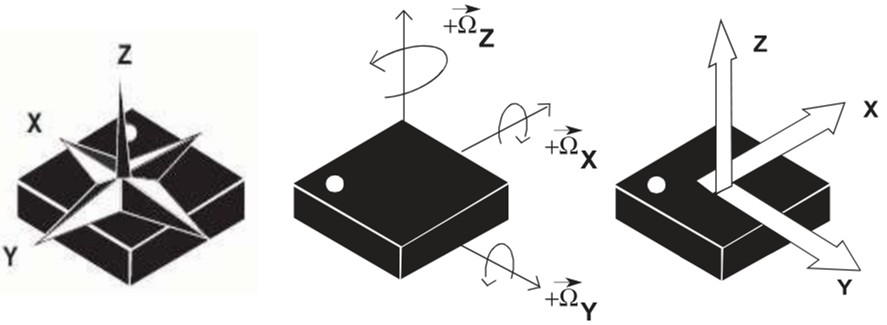
The coordinate system for my IMU is a bit wonky, so I normalized it to a right-handed coordinate system. Here is the coordinate system out of the box:

IMU coordinate system

(Note the polarity marker is rotated for the mag diagram)

Here is my normalization and scaling code (and the filter call):

imu.readGyro();
imu.readAccel();
imu.readMag();

float gx, gy, gz, ax, ay, az, mx, my, mz;

// Use a right-handed coordinate system

gx = imu.calcGyro(imu.gy);
gy = imu.calcGyro(imu.gx);
gz = imu.calcGyro(imu.gz);

ax = imu.calcAccel(imu.ay);
ay = imu.calcAccel(imu.ax);
az = imu.calcAccel(imu.az);

mx = imu.calcMag(imu.my);
my = -imu.calcMag(imu.mx);
mz = imu.calcMag(imu.mz);

// update the filter, which computes orientation
filter.update(gx, gy, gz, ax, ay, az, mx, my, mz);

// print the heading, pitch and roll
roll = filter.getRoll();
pitch = filter.getPitch();
yaw = filter.getYaw();

// Print values here

The calcX calls are part of the IMU library, described in short:

calcAccel(), calcGyro(), and calcMag()

The library keeps track of each sensor’s scale, and it implements these helper functions to make translating between the raw ADC readings of the sensor to actual units easy.

calcAccel(), calcGyro(), and calcMag() all take a single parameter – a signed 16-bit integer – and convert to their respective units. They all return a float value, which you can do with as you please.

I tried to keep this short, and I appreciate any time anyone can spend on it. I'm also including the full sketch for context if needed.

Pitch and yaw reversed in Visualizer

I noticed a minor issue in the visualizer example : the pitch and yaw angles are reversed.
When i rotate the board in one direction along one of these axes, the visualization rotate in the opposite direction.

Yaw values in the sample code (visualize)

A small change in the actual object's (say board) orientation (Yaw) is changing both the Yaw and Roll values given by the library by a lot. But, the visualizer is showing the orientation changes correctly.

When I changed just the Yaw of the board by approximately 10 degrees, the values returned by the library changed from 258.55 -76.74 -78.69 to 107.18 -83.89 82.95.

Don't the Yaw, Pitch, Roll values returned by the library represent the rotations about axes ?
Why can't we use the Yaw, Pitch, Roll values directly to rotate the 3D object (Instead of applying matrix transformations) ?

Issues on how to use ur code to process data from cell phone's inner sensors

I m now working on heading estimation and trying to use madgwick algo in ur project processing cell phone's acceleration ,magnetometer and gyroscope data to get heading information. I tried inputing raw data into update() function and the result of ypr angle seems pretty strange. I m not sure if i use the
ax = convertRawAcceleration(aix); ay = convertRawAcceleration(aiy); az = convertRawAcceleration(aiz); gx = convertRawGyro(gix); gy = convertRawGyro(giy); gz = convertRawGyro(giz); code after getting my raw data, and i also wanna know how to transfer the ypr angle result to pedestrian‘s heading.

`strict-aliasing` warnings

In the desktop IDE I get a couple of "warnings" but in the ONLINE editor CREATE I get a compilation failure with the following output.

/home/admin/builder/arduino-builder/latest/Madgwick-1.2.0/src/MadgwickAHRS.cpp: In static member function ‘static float Madgwick::invSqrt(float)’:
/home/admin/builder/arduino-builder/latest/Madgwick-1.2.0/src/MadgwickAHRS.cpp:234:20: warning: dereferencing type-punned pointer will break strict-aliasing rules [-Wstrict-aliasing]
long i = *(long*)&y;
^
/home/admin/builder/arduino-builder/latest/Madgwick-1.2.0/src/MadgwickAHRS.cpp:236:16: warning: dereferencing type-punned pointer will break strict-aliasing rules [-Wstrict-aliasing]
y = *(float*)&i;
^

Orientation visualizer understanding problem

As you raised a issue here arduino/ArduinoCore-arc32#151

and you have corrected the issue using a matrix i.e

float c1 = cos(radians(roll));
float s1 = sin(radians(roll));
float c2 = cos(radians(pitch));
float s2 = sin(radians(pitch));
float c3 = cos(radians(yaw));
float s3 = sin(radians(yaw));
applyMatrix( c2_c3, s1_s3+c1_c3_s2, c3_s1_s2-c1_s3, 0,
-s2, c1_c2, c2_s1, 0,
c2_s3, c1_s2_s3-c3_s1, c1_c3+s1_s2_s3, 0,
0, 0, 0, 1);

Can you please explain the following matrix in terms simple
rotateY , rotateX, rotateZ functions

Did you also change anything in madgwick libraries ?

please help me to understand the basis of the changes.

Changes and drift in Yaw when varying Pitch/Roll

Hi,
I'm using a MPU9255 with an ESP12. Currently I'm able to use this filter, obtaining good results with the following input data:
filter.update(gx*RAD_TO_DEG, gy*RAD_TO_DEG, gz*RAD_TO_DEG, ax, ay, az, mx, my, mz);
The problem is that, in this way, I get the equivalent of an aeroplane reference system, with z axis pointing down.

Following the axis scheme of the MPU9255 and deciding to set y axis to North, I've changed the previous call with the following one using the NED reference system:
filter.update(gy*RAD_TO_DEG, gx*RAD_TO_DEG, -gz*RAD_TO_DEG, ay, ax, -az, mx, my, mz);
In this way, the sensor is giving good values with correct Roll and Pitch data.

The problem is that, whenever I start tilting the sensor (ie. incrementing Pitch), the Yaw also changes a lot, and it takes a very long time (tens of seconds) to get back in the right "pose", making the sensor useless. Any idea of why this happens? It doesn't happen with the first call reported above, which works perfectly.

Gyroscope and magnetometer have been calibrated, obtaining the results depicted in the following image (mag).

postcalibrazione_con_filtro

I also noticed that, whenever I rotate the sensor on a flat surface, the yaw is not the only value varying, but also roll/pitch. Is this normal?

Gyro and acc are running at 200Hz, mag (AK8963) at 100Hz and I've passed 200Hz to filter.begin() (I tried also with 25, 100 and 1000 values, getting equivalent results). Tried with Mahony filter, and a second IMU unit (Waveshare IMU 10DOF V2-C ), but got the same results! Data from MPU is retrieved using Bolderflight library.

Thank you.

Recommend Option be added to return the quaternions

Besides YPR the quaternions are useful to calculate dynamic acceleration as well as other coordinate transformations. I recommend a getQ function be added to the filter files. In MadgwickAHRS.cpp you could add:

void Madgwick::getQ(float * q) {
    q[0] = q0;  
    q[1] = q1;
    q[2] = q2;
    q[3] = q3;
}

while in MadgwickAHRS.h under public functions:

void getQ(float * q);

In the visualizer sketch you would need to add:
float q[4];
and obviously to call the new function:
filter.getQ(*q);

R.
Mike

Add quaternions.

A pull request has been done so that the quaternion form can be returned. Could you please accept the pull request? Thanks.

Recommend Projects

  • React photo React

    A declarative, efficient, and flexible JavaScript library for building user interfaces.

  • Vue.js photo Vue.js

    🖖 Vue.js is a progressive, incrementally-adoptable JavaScript framework for building UI on the web.

  • Typescript photo Typescript

    TypeScript is a superset of JavaScript that compiles to clean JavaScript output.

  • TensorFlow photo TensorFlow

    An Open Source Machine Learning Framework for Everyone

  • Django photo Django

    The Web framework for perfectionists with deadlines.

  • D3 photo D3

    Bring data to life with SVG, Canvas and HTML. 📊📈🎉

Recommend Topics

  • javascript

    JavaScript (JS) is a lightweight interpreted programming language with first-class functions.

  • web

    Some thing interesting about web. New door for the world.

  • server

    A server is a program made to process requests and deliver data to clients.

  • Machine learning

    Machine learning is a way of modeling and interpreting data that allows a piece of software to respond intelligently.

  • Game

    Some thing interesting about game, make everyone happy.

Recommend Org

  • Facebook photo Facebook

    We are working to build community through open source technology. NB: members must have two-factor auth.

  • Microsoft photo Microsoft

    Open source projects and samples from Microsoft.

  • Google photo Google

    Google ❤️ Open Source for everyone.

  • D3 photo D3

    Data-Driven Documents codes.