Code Monkey home page Code Monkey logo

reallyusefulrobot's Introduction

ReallyUsefulRobot

Hardware

CAD files are provided in STEP/STP format. This is the whole assembly as a solid format so you can easily edit it. You will need to load it into some CAD software and edit/export individual STLs for printing.

Tyres are printed in TPU, I used Ninjaflex. The rest in PLA printed with a combination of 0.5mm and 1.2mm nozzles.

Motors are 6374 150Kv BLDC motors from the ODrive store: https://odriverobotics.com/shop Encoders and cables are the 8192 CPR encoders also from the ODrive store. I used a 56V ODrive 3.6, the robot runs from a 24V LiPo, but it can be 25V+ when it's charged. Wheel Drive belts are 590mm T5 12mm wide PU belts with steel tensioners made by Synchroflex. 'Utility Stick' drive belt is an HTD 5mm pitch 15mm wide 1790mm length belt.

Other electronics so far include:

-Teensy 4.1 -NVIDIA Xavier NX -RPLIDAR A2 -24v and 11.1v lipos, switches and wiring etc

Software

Obviously this isn't a comprehensive guide to ROS, you will need to undestand some core concepts before building this. The Robot runs ROS Melodic on Ubuntu 18.04. This is because the NVIDIA Xavier NX runs 18.04 by default.

On the robot:

The arduino code runs on the Teensy 4.1. This talks to the wheel encoders. It subscribres to the cmd_vel topic and publishes Odom, and TF for the robot's motions. The RPLIDAR A2 node publishes the scan topic: https://github.com/robopeak/rplidar_ros

The Teensy also talks to the ODrive on Serial1. In order to get the ROS Serial library running on the Teensy 4.1, and get both the ROS Serial library and the ODrive library to run together I had to make various modifications. I removed mentions of the Stream Operator which were in the original ODrive Arduino example: https://github.com/madcowswe/ODrive/tree/master/Arduino/ODriveArduino/examples/ I also had to modify the ROS Serial library to add Teensy 4.1 support, and increase buffers so that the Odom message could be published over Serial. I've included both modified libraries as zip files.

The 'rur' and 'rur_description' ROS packages are installed on the robot, and everything is launched with the 'rur_bringup.launch' file. This launches the ROS Serial node to talk tot he Teensy 4.1, starts the laser, and also uses the Robot & Joint State Publishers to publish the transform in the URDF file so the laser is linked to the robot base in the right place.

On my remote workstation:

The 'rur_navigation' ROS package is installed on the remote workstation (although it could be run locally). You will also need to install the ROS navigation stack and slam_gmapping. You will also need to run rosdep to install any other dependencies: http://wiki.ros.org/rosdep

https://github.com/ros-planning/navigation/tree/melodic-devel https://github.com/ros-perception/slam_gmapping/tree/melodic-devel

There is no launch file for gmapping, so having launched the rur_bringup package on the robot and launched Gmapping ( rosrun gmapping slam_gmapping scan:=scan ) you'll have to open Rviz and manually add/connect the topics for TF/Laser/Map etc. You can use the map server/saver command to save the map ( rosrun map_server map_saver -f ~/map )

After the map is complete you can launch the rur_navigation package which will open Rviz automatically. Use: roslaunch rur_navigation rur_navigation.launch map_file:=$HOME/map.yaml to connect to the map you saved.

Simulation

NOTE: The following content in the README includes implementation and documentation of Simulation package of ReallyUsefulRobot and is being made by Pranshu Tople and is been documented LIVE on his YouTube Playlist. James Bruton is not responsible if the following simulation package has any issues. So if face any problem in simulation, you can open up a GitHub Issue and tag Pranshu Tople's Github Account. Hope you enjoy Simulating ReallyUsefulRobot on your PC ☺️✌🏼

Fusion2URDF Teleoperation & Gazebo Plugins Mapping in Simulation Navigation in Simulation

You don't have to worry anymore if you don't have enough capital to build the RUR robot! You can simply follow the guide given below, and you will have simulation of RUR running on your PC without any issue. The simulation works exactly like the real robot and communicates on the same topic lists. So if you make some software or package for simulated robot, the same would work on real RUR robot without any problem. This opens up gates for the Open-Source community to build various different applications around RUR.

Downloading Pre-requisites

If you have not downloaded the full-desktop-version of ROS which comes with Gazebo Simulator, then you might need to download a couple of pre-requisites to run the simulation. Even if you have downloaded the full version, yet its a good practice to run the following command which checks if all the pre-requisites are installed or not. And if they are not installed, then the same command downloads them all automatically.

sudo apt-get install gazebo9 libgazebo9-* ros-melodic-robot-state-publisher ros-melodic-robot-joint-state-publisher ros-melodic-robot-joint-state-publisher-gui ros-melodic-teleop-twist-keyboard ros-melodic-gmapping ros-melodic-slam-gmapping ros-melodic-map-server

Testing the simulation

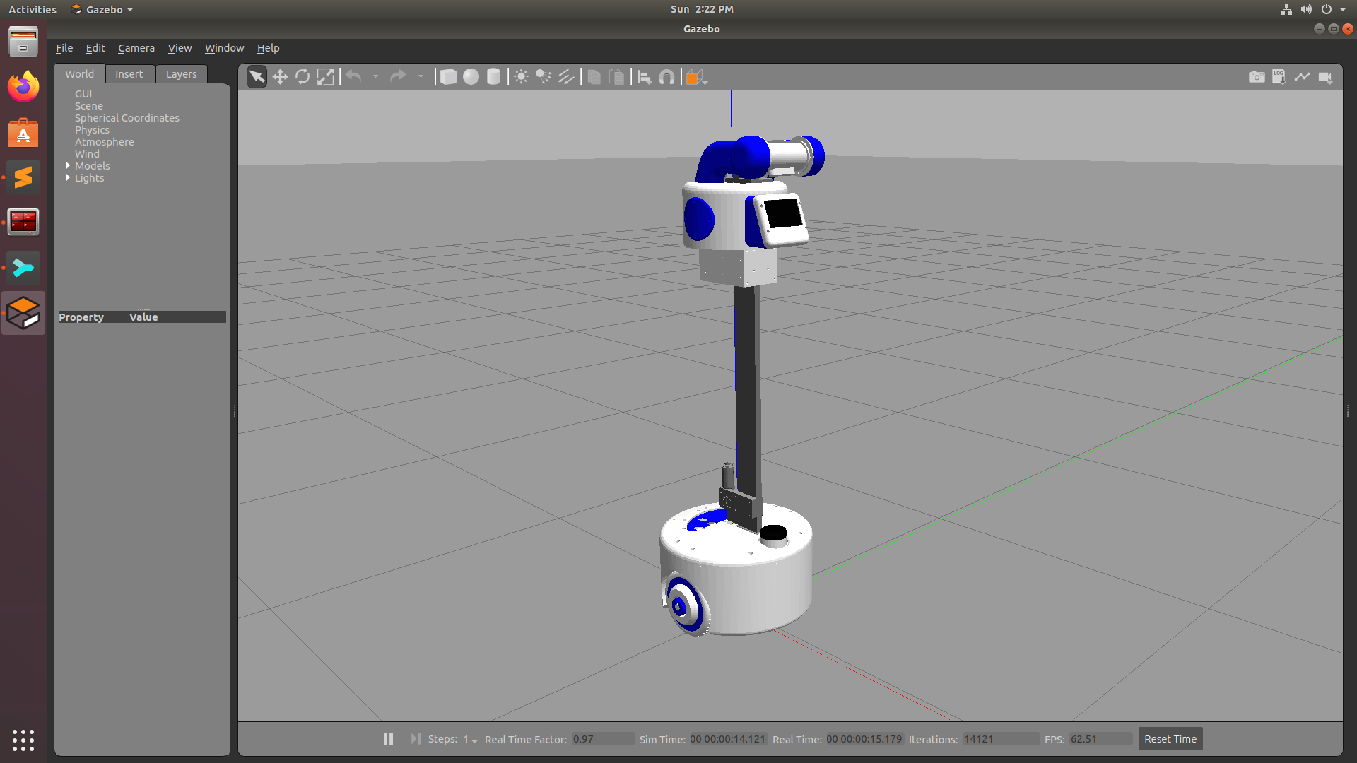
Firstly, please place this complete repository or just the ROS folder into your src folder of catkin_ws and run catkin_make command. Once the catkin_make is done successfully, then to launch the robot in an empty simulation world for testing in Gazebo Simulator, run the following command on your terminal

roslaunch rur_detailed_description gazebo.launch

Once you have successfully launched the simulation, you can also run the Teleop node to teleoprate you robot using keyboard. To run the node, paste the following command in a new terminal and you can move your robot around using ' i ' ,' j ' , ' k ' , ' l ' , ' , '

  • i = move forward
  • k = stop
  • j = rotate left
  • l = rotate right
  • , = move backward
  • along with few more operations like 'u','o','m','.' to go forward-left, forward-right, backward-left and backward-right respectively
rosrun teleop_twist_keyboard teleop_twist_keyboard.py

You can also add a couple of obstacles in the environment and check if the LiDAR is able to detect them. Just run the following command and it will open up RViz which is a robot visualization tool that helps you visualize sensor data from the robot.

roslaunch rur_detailed_description display.launch

RViz is also a place where you can closely inspect the URDF of the robot and look at the detailed TF structer of the robot

Running the RUR in a simulated world

Once you have tested that both Gazebo and RViz are working properly, then comes the part where you can actually simulate the robot in a virtual world and do mapping and navigation. Just like we run 'rur_bringup.launch' file while working on real robot similarly to start the simulation, we need to launch the 'rur_house.launch' file that will launch gazebo with RUR in a house environment. You can also run 'display.launch' file to view the LiDAR data at the same time. This eleminates the step of manually opening RViz for mapping and setting up different parameters

roslaunch rur_gazebo rur_house.launch
roslaunch rur_detailed_description display.launch

Mapping

The command of mapping is the same as the original robot. Just you don't need to open up RViz separetly as you already have 'display.launch' running.

rosrun gmapping slam_gmapping scan:=scan

Also you can run the teleop node in a separate terminal and move the robot around

Once you have completed generating the map, before saving the map, navigate to the directory where you want to save the map through your terminal and run the following command to save it.

rosrun map_server map_saver -f name_of_map

You can then navigate to the directory from your file manager to check if the map is properly saved

Navigation

To run naviagtion, firstly you have to make sure that the simulation is running properly. Run the following command to start the simulation

roslaunch rur_gazebo rur_house.launch

Once you have the simulation running properly with the robot spawned in the middle, now you can run the same navigation file which is used to start navigation on the real robot that is -

roslaunch rur_navigation rur_navigation.launch

But here, you dont need to give any location of the map as the default location of the map is set to the house map. If you want to pass some other map, then you can pass the respective argument. There is no need to launch 'display.launch' as this will start RViz automatically and you can give 2D Nav Goal to the robot

Once you give the navigation goal, the robot will start navigating to the goal location autonomously in Gazebo and you can visualize that in RViz at the same time. Once you reach the Goal, you will also get a prompt on the terminal that the robot has Reached the Goal...

Everything related to Simulation you see on this repository was streamed & documented LIVE on Youtube. To Learn more about the Simulation Package in detail and if you wish to see how is it implemented, then check out the following Playlist on Youtube

If you have any doubts or questions regarding simulation, then either you can comment that on Youtube or else open a Github Issue.

reallyusefulrobot's People

Contributors

pranshutople avatar xrobots avatar

Stargazers

 avatar  avatar  avatar  avatar  avatar  avatar  avatar  avatar  avatar  avatar  avatar  avatar  avatar  avatar  avatar  avatar  avatar  avatar  avatar  avatar  avatar  avatar  avatar  avatar  avatar  avatar  avatar  avatar  avatar  avatar  avatar  avatar  avatar  avatar  avatar  avatar  avatar  avatar  avatar  avatar  avatar  avatar  avatar  avatar  avatar  avatar  avatar  avatar  avatar  avatar  avatar  avatar  avatar  avatar  avatar  avatar  avatar  avatar  avatar  avatar  avatar  avatar  avatar  avatar  avatar  avatar  avatar  avatar  avatar  avatar  avatar  avatar  avatar  avatar  avatar  avatar  avatar  avatar  avatar  avatar  avatar  avatar  avatar  avatar  avatar  avatar  avatar  avatar  avatar  avatar  avatar  avatar  avatar  avatar  avatar  avatar  avatar  avatar  avatar  avatar

Watchers

 avatar  avatar  avatar  avatar  avatar  avatar  avatar  avatar  avatar  avatar  avatar  avatar  avatar  avatar  avatar  avatar  avatar  avatar

reallyusefulrobot's Issues

Robot vibrating

Hello,
The simulation worked fine for me, although the robot always gets stuck on a narrow passage during autonomous navigation. However, I am trying to implement this on the real robot but no luck at the moment.
I have an ODrive controller 56v v3.6, Arduino mega and jetson nano but a different wheel (hoverboard 165.1 mm wheel diameter).
When I run the Arduino ROS serial node, the wheel spins but with heavy vibration. I anticipate it could be errors due to the encoder and wheel parameters calculation. Also, the robot moves quite slow in RViz (sometimes unnoticeable) compared to real-time.
I am wondering if you could spare some time to assist me to fix it?.

Thank you for your time and in anticipation of your response

Running navigation stack and Gmapping in On-board raspberry Pi

Hi james. Can i ask you something about this project. Did you run all the Gmapping node and Navigation stack all on Raspberry Pi onboard or some of them in remote computer with SSH ? i also built the same system like you now, but can't figure out why the map update keep missing it's desired rate. I suspect some computation issue, but seeing your video with the same setting as me, it looks all good.

Robot in Rviz doesnt move straight correctly

i have played around and converted the wheel calculation to the new odrive standards, using this equation Turns = Counts/EncoderCpr

everything works perfectly except the odometry messages not sending the correct orientation of the robot. more like it is oscillating right and left while moving forward.
here is a link of the movement: https://youtu.be/_V9KNEuVXbw
and the low refresh rate is also a problem :(
do keep in mind the robot is connected to the pc and the data of the movement is coming from odom

the only different thing I'm using is Teensy 4.0

I'm using the First upload of the
here is the Arduino code:

#include <ODriveArduino.h>

//ODrive Objects
ODriveArduino odrive1(Serial1);

//ROS
#include "ros.h"
#include "geometry_msgs/Twist.h"
#include <ros/time.h>
#include <tf/tf.h>
#include <tf/transform_broadcaster.h>
#include <nav_msgs/Odometry.h>
#include <geometry_msgs/Vector3.h>

ros::NodeHandle nh;
geometry_msgs::TransformStamped t;
nav_msgs::Odometry odom_msg;
ros::Publisher odom_pub("odom", &odom_msg);
tf::TransformBroadcaster broadcaster;

// tf variables to be broadcast
double x = 0;
double y = 0;
double theta = 0;

char base_link[] = "/base_link";
char odom[] = "/odom";

// cmd_vel variables to be received to drive with
float demandx;
float demandz;

// timers for the sub-main loop
unsigned long currentMillis;
long previousMillis = 0; // set up timers
float loopTime = 10;

// ODrive init stuff
int button;
int requested_state;

// output variables to drive the ODrive
int forward0;
int forward1;
int turn0;
int turn1;

// position and velocity variables read from the ODrive
int vel0;
int vel1;
long pos0;
long pos1;

// variables to work out the different on each cycle

long pos0_old;
long pos1_old;
long pos0_diff;
long pos1_diff;
float pos0_mm_diff;
float pos1_mm_diff;
float pos_average_mm_diff;
float pos_total_mm;

// ** ROS callback & subscriber **

void velCallback( const geometry_msgs::Twist& vel)
{
demandx = vel.linear.x;
demandz = vel.angular.z;
}

ros::Subscriber<geometry_msgs::Twist> sub("cmd_vel" , velCallback);

// ** Setup **

void setup() {

nh.getHardware()->setBaud(115200);      // set baud rate to 115200
nh.initNode();              // init ROS
nh.subscribe(sub);          // subscribe to cmd_vel
nh.advertise(odom_pub);
broadcaster.init(nh);       // set up broadcaster

pinMode(2, INPUT_PULLUP);   // ODrive init switch

Serial1.begin(115200);    // ODrive
Serial6.begin(115200);    // debug port using a USB-serial adapter (Serial-zero is in use by ros_serial

}

// ** Main loop **

void loop() {

nh.spinOnce();        // make sure we listen for ROS messages and activate the callback if there is one

currentMillis = millis();
      if (currentMillis - previousMillis >= loopTime) {  // run a loop every 10ms          
          previousMillis = currentMillis;          // reset the clock to time it

          button = digitalRead(2);                 // init ODrive
          if (button == 0) {
            OdriveInit1();
          } 

          float modifier_lin = 1.03;        // scaling factor because the wheels are squashy / there is wheel slip etc.
          float modifier_ang = 1.5;        // scaling factor because the wheels are squashy / there is wheel slip etc.


          forward0 = demandx * ((83466/8192) * modifier_lin) ; // convert m/s into counts/s
          forward1 = demandx * ((83466/8192) * modifier_lin); // convert m/s into counts/s

          turn0 = demandz * ((15091/8192) * modifier_ang);    // convert rads/s into counts/s
          turn1 = demandz * ((15091/8192) * modifier_ang);    // convert rads/s into counts/s

          forward1 = forward1*-1;      // one motor and encoder is mounted facing the other way

          odrive1.SetVelocity(0, forward0 + turn0); 
          odrive1.SetVelocity(1, forward1 + turn1);

          // get positions and velocities from ODrive

          pos0 = (odrive1.GetPosition(1)) *-1;                   
          pos1 = odrive1.GetPosition(0);   

          // work out the difference on each loop, and bookmark the old value
          pos0_diff = pos0 - pos0_old;
          pos1_diff = pos1 - pos1_old;            
          pos0_old = pos0;
          pos1_old = pos1;
  
          // calc mm from encoder counts
          pos0_mm_diff = pos0_diff / 83.44*8192;
          pos1_mm_diff = pos1_diff / 83.44*8192;

          // calc distance travelled based on average of both wheels
          pos_average_mm_diff = (pos0_mm_diff + pos1_mm_diff) / 2;   // difference in each cycle
          pos_total_mm += pos_average_mm_diff;                       // calc total running total distance

          // calc angle or rotation to broadcast with tf
          float phi = ((pos1_mm_diff - pos0_mm_diff) / 360);

          theta += phi;
        
          if (theta >= TWO_PI) {
              theta -= TWO_PI;
          }
          if (theta <= (-TWO_PI)) {
              theta += TWO_PI;
          }

          // calc x and y to broadcast with tf

          y += pos_average_mm_diff * sin(theta);
          x += pos_average_mm_diff * cos(theta);

          // *** broadcast odom->base_link transform with tf ***

          geometry_msgs::TransformStamped t;
                    
          t.header.frame_id = odom;
          t.child_frame_id = base_link;
          
          t.transform.translation.x = x/1000;   // convert to metres
          t.transform.translation.y = y/1000;
          t.transform.translation.z = 0;
          
          t.transform.rotation = tf::createQuaternionFromYaw(theta);
          t.header.stamp = nh.now();
                     
          broadcaster.sendTransform(t); 

          // *** broadcast odom message ***

          nav_msgs::Odometry odom_msg;
          odom_msg.header.stamp = nh.now();
          odom_msg.header.frame_id = odom;
          odom_msg.pose.pose.position.x = x/1000;
          odom_msg.pose.pose.position.y = y/1000;
          odom_msg.pose.pose.position.z = 0.0;
          odom_msg.pose.pose.orientation = tf::createQuaternionFromYaw(theta);

          odom_msg.child_frame_id = base_link;
          odom_msg.twist.twist.linear.x = ((pos0_mm_diff + pos1_mm_diff) / 2)/10;          // forward linear velovity
          odom_msg.twist.twist.linear.y = 0.0;                                        // robot does not move sideways
          odom_msg.twist.twist.angular.z = ((pos1_mm_diff - pos0_mm_diff) / 360)*100;      // anglular velocity

          odom_pub.publish(&odom_msg);

      } // end of 10ms loop

} // end of main loop

.

Consolidated BOM

Do you think it'd be possible to add a consolidated BOM somewhere? Most of the large non-printed parts, like the major electronic components, are mentioned in the README or in the videos, but there are still some things I'm not sure what / where to buy, such as:

  • the springs for the base suspension
  • the casters
  • the vertical timing belt (and maybe some other components to the vertical drive that I missed)
  • fasteners (I know use use 2.9mm self tapping threads in a few places, but it seems there's at least one other kind of fastener)
  • the bearings (though I could probably figure this out at least)

I know it might be a bit tedious, especially with the fasteners, but I think it'd be a big help to people trying to recreate this project.

If you want to send me a CSV / spreadsheet / Google Sheet link, I can also help format the BOM as a Github Markdown table if you'd like, perhaps in the README.

Thanks!

Some tips on ROS

Cool project! I watched your video and really enjoyed it. While watching, I realized that I've seen several other of your videos over the years and liked them a lot.

Your skills in many areas surpass my own by far. However, since I've been developing ROS software for a living for 10 years, this is one area where I figured I could help, and I couldn't resist giving you some unsolicited advice, so here goes.

Aligning depth and color images

Instead of this hackery:

detectXa = int((detectX/640*400)+100) # scale and shift for RGB/depth camera alignment
detectYa = int((detectY/480*240)+100) # scale and shift for RGB/depth camera alignment

... you should either use pyrealsense2.rs2_project_color_pixel_to_depth_pixel, or perhaps better yet don't use the pyrealsense2 library, but instead use the realsense2_camera ROS driver something like this (adjust width + height as needed):

<include file="$(find realsense2_camera)/launch/rs_rgbd.launch">
  <arg name="camera"          value="d435" />

  <arg name="depth_width"     value="848"/>
  <arg name="depth_height"    value="480"/>
  <arg name="enable_depth"    value="true"/>

  <arg name="infra_width"     value="848"/>
  <arg name="infra_height"    value="480"/>
  <arg name="enable_infra1"   value="true"/>
  <arg name="enable_infra2"   value="true"/>

  <arg name="color_width"     value="848"/>
  <arg name="color_height"    value="480"/>
  <arg name="enable_color"    value="true"/>

  <arg name="enable_sync"     value="true"/>
  <arg name="align_depth"     value="true"/>
</include>

From the realsense-ros README:

align_depth: If set to true, will publish additional topics for the "aligned depth to color" image.: /camera/aligned_depth_to_color/image_raw, /camera/aligned_depth_to_color/camera_info.

Since we set the camera parameter to d435, this will be /d435/aligned_depth_to_color/image_raw instead.

Then you can use a TimeSynchronizer to subscribe to the /d435/aligned_depth_to_color/image_raw and /d435/color/image_raw topics, and they will be aligned pixel-by-pixel; in other words, the depth image will be transformed to look as if the depth camera was exactly at the RGB camera's position and also as if it had the same camera parameters (lens distortion etc.) as the RGB camera.

Removing lens distortion

There should also be two topics called .../image_rect_raw and .../image_rect_color. These are the rectified topics, i.e. any lens distortion has been removed. You should use those if you're going to use some trigonometry like you showed in the video.

Using TF

Regarding the trigonometry calculations, you can make your life much easier by using the tf2_ros library. There are some tutorials that are 100% worth going over. TF is one part where ROS really shines.

In short, you should:

  • Remove the joint_state_publisher from your rur_bringup launch file.
  • Publish the angle of the camera tilt unit as a sensor_msgs/JointState message on the topic /joint_states instead of a std_msgs/UInt16 as you're doing now. You can leave the velocity and effort fields empty, just fill in the name field with the name of the joint in the URDF and the position field with the joint angle in radians.
  • Do the same for the wheel joints. The joint_states topic can have multiple independent publishers, they don't all need to be in one message.
  • Add the arm to your URDF and also publish joint_states for them.

This will allow the robot_state_publisher to pick up the actual joint states from your robot, display them in RViz and (most importantly) publish correct TFs for them.

Now is where the magic happens: You can now automatically transform the center point of your cup into any frame (base_link, or your gripper frame, or whatever). Disclaimer: I haven't tested the code below, but it should give you the right ideas:

import rospy
import message_filters
import tf2_geometry_msgs
import tf2_ros

from image_geometry import PinholeCameraModel

from geometry_msgs.msg import PointStamped
from sensor_msgs.msg import Image, CameraInfo


class VisionNode(object):
    def __init__(self):
        self.camera_model = PinholeCameraModel()

        self.tf = tf2_ros.Buffer()
        self.tfl = tf2_ros.transform_listener.TransformListener(tf)

        self.color_image_sub = message_filters.Subscriber(
            "/d435/color/image_rect_color", Image, queue_size=1
        )
        self.depth_image_sub = message_filters.Subscriber(
            "/d435/aligned_depth_to_color/image_rect_raw", Image, queue_size=1
        )
        self.info_sub = message_filters.Subscriber(
            "/d435/color/camera_info", CameraInfo, queue_size=1
        )

        self.ts = message_filters.TimeSynchronizer(
            [color_image_sub, depth_image_sub, info_sub], 1
        )
        self.ts.registerCallback(callback)

    def callback(color_image, depth_image, camera_info):
        # TODOs:
        # - compute detectX, detectY as in previous code
        # - look up detectZ for those pixel coordinates from depth image

        # compute 3D point (in camera frame)
        self.camera_model.fromCameraInfo(camera_info)
        (x, y, z) = self.camera_model.projectPixelTo3dRay((detectX, detectY))
        p = PointStamped()
        p.header = color_image.header
        p.point.x = x * detectZ
        p.point.y = y * detectZ
        p.point.z = detectZ

        # automagically transform into any frame
        tf.transform(p, "base_link")


def main():
    rospy.init_node("vision")
    VisionNode()
    try:
        rospy.spin()
    except rospy.ROSInterruptException:
        pass


if __name__ == "__main__":
    main()

Controlling the arm

If you want to go in really deep, look at MoveIt. It's not going to be easy though!

Joint state publisher GUI

Bonus tip: If you use the joint_state_publisher_gui in your display.launch like this...

  <node name="joint_state_publisher_gui" pkg="joint_state_publisher_gui" type="joint_state_publisher_gui"/>

..., it will pop up a little GUI where you can play around with the joints in your URDF. Very useful for debugging.

the robot moves faster in rviz then in real

hi... thanks for all the hardwork you put on this project and make it working.. i try your code with my robot using audriuino mega..but my robot runs faster in rviz then in real .. and i think cuz of that the navigation stack also not work..i have tried the wheel reduction ratio part and calculate the values according to my robot but still no luck..

How to change the Teensy serial port for rosserial

Hi, I have been working with the RUR programs for a couple of days and they work great! I would like to wire my teensy 4.1 to a raspberry pi for serial, rather than using usb. I tried to follow the rosserial tutorials on changing the wired serial port, but it throws me lots of errors, I am guessing this is because of the modified library. Does anyone know how I could change the teensy serial port used? Thanks!

How to attach pulley to wheels?

How are you attaching the t5 wheel pulley to the wheel? There doesn't seem to be any mounting holes for screwing them on. Are you gluing them?
I've printed them, but the pulley just spins around the wheel. Either my tolerance is off, or there's something I'm missing.

CAD for utility stick belt pulley

Do you have the CAD model, or STL, for the utility stick belt pulley? At first, I thought it would be the same as the O-Drive pulley, but it seems to have a thicker belt, and a larger pulley.

FYI, I'll probably have to find a 3D model for a similar pulley because the replacement motors I'm finding for the GR-WM2 all have 8mm shafts on them. Can you tell me me the belt size (pitch, width, and length)?

Navigation failure

I'm having trouble with the navigation stack. When I make a waypoint, my robot starts jerking around; no smooth movement. Today the robot fell over because of this. Any idea on what could cause this? Or how to fix it?

For background, I was able to get the robot moving smoothly. I had to change the arduino code to convert the Odrive turns to millimeters, but now its fine. The odom, base_link, and lazer show up in rviz. I can drive around fine, the lazer scan stays put, and I have built a map of my living room. I launched the navigation stack, the map comes up, although the costmap looks rather inflated, but the robot is oriented right, assuming I place it in my room where I started the map.

It looks like the navigation stack is continuously updating its plan. The robot never really gets a chance to drive straight; instdead it whips back and forth like a low-rent murder bot. My dogs are concerned.

(I rolled back the git repository to the original navigation commit, before the simulation stuff was merged just to be sure that wasnt the issue, but both versions have this issue. In the latest code, the lazer scan gets out of synch with the map; that doesn't happen in the original version)

Here's the log from the navigation:
roslaunch rur_navigation rur_navigation.launch map_file:=$HOME/ros_catkin_ws/src/rur_navigation/maps/livingroom_sean.yaml
... logging to /home/sean/.ros/log/546ce954-4473-11ed-920f-bfb2a73f92b8/roslaunch-beefcake-62996.log
Checking log directory for disk usage. This may take a while.
Press Ctrl-C to interrupt
Done checking log file disk usage. Usage is <1GB.

started roslaunch server http://beefcake:38965/

SUMMARY

PARAMETERS

  • /amcl/base_frame_id: base_link
  • /amcl/gui_publish_rate: 50.0
  • /amcl/initial_pose_a: 0.0
  • /amcl/initial_pose_x: 0.0
  • /amcl/initial_pose_y: 0.0
  • /amcl/kld_err: 0.02
  • /amcl/laser_lambda_short: 0.1
  • /amcl/laser_likelihood_max_dist: 2.0
  • /amcl/laser_max_beams: 180
  • /amcl/laser_max_range: 3.5
  • /amcl/laser_model_type: likelihood_field
  • /amcl/laser_sigma_hit: 0.2
  • /amcl/laser_z_hit: 0.5
  • /amcl/laser_z_max: 0.05
  • /amcl/laser_z_rand: 0.5
  • /amcl/laser_z_short: 0.05
  • /amcl/max_particles: 3000
  • /amcl/min_particles: 500
  • /amcl/odom_alpha1: 0.1
  • /amcl/odom_alpha2: 0.1
  • /amcl/odom_alpha3: 0.1
  • /amcl/odom_alpha4: 0.1
  • /amcl/odom_frame_id: odom
  • /amcl/odom_model_type: diff
  • /amcl/recovery_alpha_fast: 0.0
  • /amcl/recovery_alpha_slow: 0.0
  • /amcl/resample_interval: 1
  • /amcl/transform_tolerance: 0.5
  • /amcl/update_min_a: 0.2
  • /amcl/update_min_d: 0.2
  • /move_base/DWAPlannerROS/acc_lim_theta: 3.2
  • /move_base/DWAPlannerROS/acc_lim_x: 2.5
  • /move_base/DWAPlannerROS/acc_lim_y: 0.0
  • /move_base/DWAPlannerROS/controller_frequency: 10.0
  • /move_base/DWAPlannerROS/forward_point_distance: 0.325
  • /move_base/DWAPlannerROS/goal_distance_bias: 20.0
  • /move_base/DWAPlannerROS/latch_xy_goal_tolerance: False
  • /move_base/DWAPlannerROS/max_scaling_factor: 0.2
  • /move_base/DWAPlannerROS/max_vel_theta: 2.75
  • /move_base/DWAPlannerROS/max_vel_trans: 0.22
  • /move_base/DWAPlannerROS/max_vel_x: 0.22
  • /move_base/DWAPlannerROS/max_vel_y: 0.0
  • /move_base/DWAPlannerROS/min_vel_theta: 1.37
  • /move_base/DWAPlannerROS/min_vel_trans: 0.11
  • /move_base/DWAPlannerROS/min_vel_x: -0.22
  • /move_base/DWAPlannerROS/min_vel_y: 0.0
  • /move_base/DWAPlannerROS/occdist_scale: 0.02
  • /move_base/DWAPlannerROS/oscillation_reset_dist: 0.05
  • /move_base/DWAPlannerROS/path_distance_bias: 32.0
  • /move_base/DWAPlannerROS/publish_cost_grid_pc: True
  • /move_base/DWAPlannerROS/publish_traj_pc: True
  • /move_base/DWAPlannerROS/scaling_speed: 0.25
  • /move_base/DWAPlannerROS/sim_time: 1.5
  • /move_base/DWAPlannerROS/stop_time_buffer: 0.2
  • /move_base/DWAPlannerROS/vth_samples: 40
  • /move_base/DWAPlannerROS/vx_samples: 20
  • /move_base/DWAPlannerROS/vy_samples: 0
  • /move_base/DWAPlannerROS/xy_goal_tolerance: 0.05
  • /move_base/DWAPlannerROS/yaw_goal_tolerance: 0.17
  • /move_base/base_local_planner: dwa_local_planner...
  • /move_base/conservative_reset_dist: 3.0
  • /move_base/controller_frequency: 10.0
  • /move_base/controller_patience: 15.0
  • /move_base/global_costmap/global_frame: map
  • /move_base/global_costmap/inflation_layer/cost_scaling_factor: 5.0
  • /move_base/global_costmap/inflation_layer/enabled: True
  • /move_base/global_costmap/inflation_layer/inflation_radius: 0.3
  • /move_base/global_costmap/map_type: costmap
  • /move_base/global_costmap/obstacle_layer/combination_method: 1
  • /move_base/global_costmap/obstacle_layer/enabled: True
  • /move_base/global_costmap/obstacle_layer/inflation_radius: 0.2
  • /move_base/global_costmap/obstacle_layer/laser_scan_sensor/clearing: True
  • /move_base/global_costmap/obstacle_layer/laser_scan_sensor/data_type: LaserScan
  • /move_base/global_costmap/obstacle_layer/laser_scan_sensor/marking: True
  • /move_base/global_costmap/obstacle_layer/laser_scan_sensor/topic: scan
  • /move_base/global_costmap/obstacle_layer/observation_sources: laser_scan_sensor
  • /move_base/global_costmap/obstacle_layer/obstacle_range: 2.5
  • /move_base/global_costmap/obstacle_layer/raytrace_range: 3.5
  • /move_base/global_costmap/obstacle_layer/track_unknown_space: False
  • /move_base/global_costmap/plugins: [{'name': 'static...
  • /move_base/global_costmap/publish_frequency: 5.0
  • /move_base/global_costmap/robot_base_frame: base_link
  • /move_base/global_costmap/robot_radius: 0.225
  • /move_base/global_costmap/static_layer/enabled: True
  • /move_base/global_costmap/static_layer/map_topic: map
  • /move_base/global_costmap/static_map: True
  • /move_base/global_costmap/transform_tolerance: 1.0
  • /move_base/global_costmap/update_frequency: 5.0
  • /move_base/local_costmap/global_frame: map
  • /move_base/local_costmap/height: 5
  • /move_base/local_costmap/inflation_layer/cost_scaling_factor: 5.0
  • /move_base/local_costmap/inflation_layer/enabled: True
  • /move_base/local_costmap/inflation_layer/inflation_radius: 0.3
  • /move_base/local_costmap/map_type: costmap
  • /move_base/local_costmap/obstacle_layer/combination_method: 1
  • /move_base/local_costmap/obstacle_layer/enabled: True
  • /move_base/local_costmap/obstacle_layer/inflation_radius: 0.2
  • /move_base/local_costmap/obstacle_layer/laser_scan_sensor/clearing: True
  • /move_base/local_costmap/obstacle_layer/laser_scan_sensor/data_type: LaserScan
  • /move_base/local_costmap/obstacle_layer/laser_scan_sensor/marking: True
  • /move_base/local_costmap/obstacle_layer/laser_scan_sensor/topic: scan
  • /move_base/local_costmap/obstacle_layer/observation_sources: laser_scan_sensor
  • /move_base/local_costmap/obstacle_layer/obstacle_range: 2.5
  • /move_base/local_costmap/obstacle_layer/raytrace_range: 3.5
  • /move_base/local_costmap/obstacle_layer/track_unknown_space: False
  • /move_base/local_costmap/plugins: [{'name': 'static...
  • /move_base/local_costmap/publish_frequency: 1.0
  • /move_base/local_costmap/resolution: 0.1
  • /move_base/local_costmap/robot_base_frame: base_link
  • /move_base/local_costmap/robot_radius: 0.225
  • /move_base/local_costmap/rolling_window: True
  • /move_base/local_costmap/static_layer/enabled: True
  • /move_base/local_costmap/static_layer/map_topic: map
  • /move_base/local_costmap/static_map: False
  • /move_base/local_costmap/transform_tolerance: 0.5
  • /move_base/local_costmap/update_frequency: 2.0
  • /move_base/local_costmap/width: 5
  • /move_base/oscillation_distance: 0.2
  • /move_base/oscillation_timeout: 10.0
  • /move_base/planner_frequency: 5.0
  • /move_base/planner_patience: 5.0
  • /move_base/shutdown_costmaps: False
  • /rosdistro: noetic
  • /rosversion: 1.15.14

NODES
/
amcl (amcl/amcl)
map_server (map_server/map_server)
move_base (move_base/move_base)
rviz (rviz/rviz)

ROS_MASTER_URI=http://beefcake:11311/

process[map_server-1]: started with pid [63010]
process[amcl-2]: started with pid [63011]
process[move_base-3]: started with pid [63012]
process[rviz-4]: started with pid [63013]
[ WARN] [1664949824.319884472]: global_costmap: Pre-Hydro parameter "static_map" unused since "plugins" is provided
[ WARN] [1664949824.322084663]: global_costmap: Pre-Hydro parameter "map_type" unused since "plugins" is provided
[ INFO] [1664949824.323612027]: global_costmap: Using plugin "static_layer"
[ INFO] [1664949824.335591525]: Requesting the map...
[ INFO] [1664949824.552640402]: Resizing costmap to 4000 X 4000 at 0.050000 m/pix
[ INFO] [1664949824.638152634]: Received a 4000 X 4000 map at 0.050000 m/pix
[ INFO] [1664949824.641547153]: global_costmap: Using plugin "obstacle_layer"
[ INFO] [1664949824.648233895]: Subscribed to Topics: laser_scan_sensor
[ INFO] [1664949824.690791106]: global_costmap: Using plugin "inflation_layer"
[ WARN] [1664949824.714233355]: local_costmap: Pre-Hydro parameter "static_map" unused since "plugins" is provided
[ WARN] [1664949824.714581156]: local_costmap: Pre-Hydro parameter "map_type" unused since "plugins" is provided
[ INFO] [1664949824.715196525]: local_costmap: Using plugin "static_layer"
[ INFO] [1664949824.716935080]: Requesting the map...
[ INFO] [1664949824.723119098]: Resizing static layer to 4000 X 4000 at 0.050000 m/pix
[ INFO] [1664949824.817654056]: Received a 4000 X 4000 map at 0.050000 m/pix
[ INFO] [1664949824.822867309]: local_costmap: Using plugin "obstacle_layer"
[ INFO] [1664949824.830207345]: Subscribed to Topics: laser_scan_sensor
[ INFO] [1664949824.862274927]: Created local_planner dwa_local_planner/DWAPlannerROS
[ INFO] [1664949824.863158973]: Sim period is set to 0.10
[ INFO] [1664949825.372567819]: Recovery behavior will clear layer 'obstacles'
[ INFO] [1664949825.383337989]: Recovery behavior will clear layer 'obstacles'
[ INFO] [1664949825.460528551]: odom received!
[ INFO] [1664949838.910582055]: Got new plan
[ INFO] [1664949839.110644220]: Got new plan
[ INFO] [1664949839.310618806]: Got new plan
[ INFO] [1664949839.510602139]: Got new plan
[ INFO] [1664949839.710688622]: Got new plan
[ INFO] [1664949839.910631436]: Got new plan
[ INFO] [1664949840.110506338]: Got new plan
[ INFO] [1664949840.310614113]: Got new plan
[ INFO] [1664949840.510615518]: Got new plan
[ INFO] [1664949840.710569169]: Got new plan
[ INFO] [1664949840.910464401]: Got new plan
[ INFO] [1664949841.110492117]: Got new plan
[ INFO] [1664949841.310661979]: Got new plan
[ INFO] [1664949841.510527558]: Got new plan
[ INFO] [1664949841.710613075]: Got new plan
[ INFO] [1664949841.910624391]: Got new plan
[ INFO] [1664949842.110641782]: Got new plan
[ INFO] [1664949842.310630494]: Got new plan
[ INFO] [1664949842.510672744]: Got new plan
[ INFO] [1664949842.710608765]: Got new plan
[ INFO] [1664949842.910698871]: Got new plan
[ INFO] [1664949843.110593497]: Got new plan
[ INFO] [1664949843.310540360]: Got new plan
[ INFO] [1664949843.510582199]: Got new plan
[ INFO] [1664949843.710666019]: Got new plan
[ INFO] [1664949843.910593931]: Got new plan
[ INFO] [1664949844.110599047]: Got new plan
[ INFO] [1664949844.310571304]: Got new plan
[ INFO] [1664949844.510679543]: Got new plan
[ INFO] [1664949844.710543665]: Got new plan
[ INFO] [1664949844.910458401]: Got new plan
[ INFO] [1664949845.110632632]: Got new plan
[ INFO] [1664949845.310576916]: Got new plan
[ INFO] [1664949845.510588454]: Got new plan
[ INFO] [1664949845.710548413]: Got new plan
[ INFO] [1664949845.910618182]: Got new plan
[ INFO] [1664949846.110646003]: Got new plan
[ INFO] [1664949846.310541918]: Got new plan
[ INFO] [1664949846.510692447]: Got new plan

Question - faisability and estimated replication time

Hello,

I'm currently pursuing a PhD in robotics, specifically about autonomous exploration and reconstruction of an unknown environment. We are currently using another platform for the project but it is not so reliable mechanically, and seeing the design of the RUR, it seems like it would be a great alternative for us, especially given we use very similar sensors (same LiDAR and a Kinect for RGBD vision). We would probably use an arm-less version since we don't plan any manipulation tasks yet.

I am currently discussing with my supervisors the possibility to try and replicate the RUR during my PhD but it is a bit difficult for me to estimate the time it would take for a team of 1-3 people to rebuild it; we have pretty good knowledge in the team about 3D printing and mechanical assembly so this should not be an issue, it's more on the electronics side that I'm not so sure about the difficulty of such an assembly. This leads me to the following questions :

  • how long do you think it would approximately take to wire, test and integrate the wheeled-base electronics with the mechanical assembly for a team of 1-3 people with a beginner/intermediate level in electronics ?
  • do you see any steps in the building process that we would need to pay special attention to ?
  • if we end up rebuilding and using the RUR for a research project, how would you prefer to be credited (YouTube channel, website, you directly) ?

Thanks in advance for any feedback about this and for the great inspiration your work is in general !
Thibault

Wiring diagram?

Is there a wiring diagram for this robot?
I'm trying to understand how the relay, switches, voltmeters, and control boards are connected.

Explanation

I have the same Odrive controller, but I am building 6-wheeled robot so I have three of them and I am using an Arduino and Jetson Nano as the brain of the robot. I can not publish Odom from Arduino, so I am sending pos0, pos1 and nh.now() to c++ node running on Jetson and the node on Jetson fix the rest exactly as u do. I get everything working fine but the robot move very fast while it is moving very slow in Rviz and I believe that is because u are using different wheel size and so on. But I can not see where u input ur wheel size and wheel separation and so on. I am wondering if you can point out where u do that and if you can explain quickly what is the values 83466,15091 and 83.44 respectively in lines 112, 115 and 135.

How to attach tires to wheel?

Does anyone have any tips on how to attach the TPU tires to the wheel? I can't tell if the tolerance is off, or if I'm just weak, but I cannot get the tires around the wheel.

Mounting hole diameters

I noticed a few holes in the assembly where two parts are joined by a screw have the same inner diameter for the portion the screw should pass through (the clearance portion) as well as the part the screw should be threaded in to. Is this actually how it's printed? I might expect the inner diameter of the part the screw should thread in to to be slightly smaller or something, either to tap the hole or so a screw can self-thread. Or I might expect the holes-for-threads to be somewhat wider than the clearance holes to accept a heat set insert or something.

Two specific cases I'm looking at now:

  • between the 4 walls of the body and each of the plates that connects the pairs of walls together
  • between the two halves of the Jetson mount
    ...there might also be others I'm not seeing right now, but I assume the answer is the same everywhere.

What kinds of fasteners do you use in these cases? Just a screw (self-tapping?), some kind of thread insert, or something else?

Thanks!

TF error

Hi James,
Im really struggling with one last bit. When i launch the rur_navigation package on my remote workstation i get two errors "no transform from Laser to Map and no transform from Base_link to Map. Im really stuck, can you point me in the right direction?

Thanks
Chris

Tire TPU infill

What infill did you print your TPU tires with?

Googling around it seems like the 85A hardness Ninjaflex is the most common (and perhaps also the only one called just "Ninjaflex", but I'm not sure). Do you know whether this is also the hardness of the Ninjaflex you used?

Thanks again.

Timed out waiting for transform from base_link to map to become available before running costmap, tf error: canTransform: target_frame map does not exist.. canTransform returned after 0.100065 timeout was 0.1

Hello

I am running into issues when running roslaunch rur_navigation rur_navigation.launch with roslaunch rur rur_bringup.launch.
This is the error:

process[map_server-1]: started with pid [27581]
process[amcl-2]: started with pid [27582]
process[move_base-3]: started with pid [27583]
process[rviz-4]: started with pid [27596]
[ WARN] [1641341048.747458020]: Request for map failed; trying again...
[ WARN] [1641341053.709191464]: Timed out waiting for transform from base_link to map to become available before running costmap, tf error: canTransform: target_frame map does not exist.. canTransform returned after 0.100065 timeout was 0.1.
[ WARN] [1641341058.731377300]: Timed out waiting for transform from base_link to map to become available before running costmap, tf error: canTransform: target_frame map does not exist.. canTransform returned after 0.1003 timeout was 0.1.
[ WARN] [1641341063.771360315]: Timed out waiting for transform from base_link to map to become available before running costmap, tf error: canTransform: target_frame map does not exist.. canTransform returned after 0.100305 timeout was 0.1.
[ WARN] [1641341065.510832061]: No laser scan received (and thus no pose updates have been published) for 1641341065.510745 seconds.  Verify that data is being published on the /scan topic.
[ WARN] [1641341068.811848131]: Timed out waiting for transform from base_link to map to become available before running costmap, tf error: canTransform: target_frame map does not exist.. canTransform returned after 0.100372 timeout was 0.1.

I am not sure where the error is coming from. Thanks in advance.

GR-WM2 replacement?

Is it possible to source the GR-WM2 somewhere? Or is there a suitable replacement?

Looks like the carriage motor has been discontinued: https://gimsonrobotics.co.uk/categories/dc-electric-motors/products/gr-wm2-24v-dc-rs-595-motor-with-152-1-gearbox?fbclid=IwAR0d2dX7y88nv4W90gfV4aULetfhDwCAWDCMk14pTz_aJ7J1FpBhlCw4sK0

They have a replacement, but it has some issues:
(a) the motor (gearbox) mounting holes are only on one side, which might not allow for enough support from the 3D printed mounts
(b) I expect the shaft won't be lined up the same as the GR-WM2. The belt needs to be driven vertically to move the carriage, which means we'd have to redesign the CAD to line up the motor, idler, and carriage.

Issue (a) isn't that big of a deal, I could fab a piece of aluminum/steel to securely mount the motor, but issue (b) is a big deal for me. It requires some CAD redesign I don't have the chops for. Also, I expect any replacement will have this same issue unless the shaft offset is exactly the same.

Recommend Projects

  • React photo React

    A declarative, efficient, and flexible JavaScript library for building user interfaces.

  • Vue.js photo Vue.js

    🖖 Vue.js is a progressive, incrementally-adoptable JavaScript framework for building UI on the web.

  • Typescript photo Typescript

    TypeScript is a superset of JavaScript that compiles to clean JavaScript output.

  • TensorFlow photo TensorFlow

    An Open Source Machine Learning Framework for Everyone

  • Django photo Django

    The Web framework for perfectionists with deadlines.

  • D3 photo D3

    Bring data to life with SVG, Canvas and HTML. 📊📈🎉

Recommend Topics

  • javascript

    JavaScript (JS) is a lightweight interpreted programming language with first-class functions.

  • web

    Some thing interesting about web. New door for the world.

  • server

    A server is a program made to process requests and deliver data to clients.

  • Machine learning

    Machine learning is a way of modeling and interpreting data that allows a piece of software to respond intelligently.

  • Game

    Some thing interesting about game, make everyone happy.

Recommend Org

  • Facebook photo Facebook

    We are working to build community through open source technology. NB: members must have two-factor auth.

  • Microsoft photo Microsoft

    Open source projects and samples from Microsoft.

  • Google photo Google

    Google ❤️ Open Source for everyone.

  • D3 photo D3

    Data-Driven Documents codes.