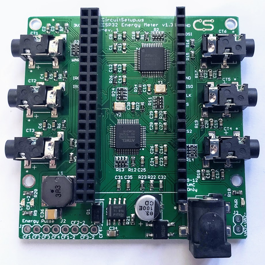
The Expandable 6 Channel ESP32 Energy Meter can read 6 current channels and 2 voltage channels at a time. Much like our Split Single Phase Energy Meter, the 6 channel uses current transformers and an AC transformer to measure voltage and power the board(s)/ESP32. The main board includes a buck converter to power the electronics and ESP32 dev board, which plugs directly into the board. Up to 6 add-on boards can stack on top of the main board to allow you to monitor up to 42 current channels in 16-bit resolution, in real time, all at once!
- North American split single phase 120V/240V 60Hz - mains and/or individual circuits
- European single phase 240V 50Hz (must provide AC-AC transformer 9V or 12V with at least 500mA output)
- 3 phase - It is recommended to measure all 3 voltages with 3 voltage transformers. This can be done by using a main board with 1 add-on board (more information below). A single meter can be used to measure 3-phase, but power (wattage) will not be calculated correctly. Power can be calculated in software, but the power factor will have to be estimated ((voltage*current)*power_factor)).
- Samples 6 current channels & 1 voltage channel (expandable to 2 voltage)
- Add-on boards (up to 6) can expand the meter up to 42 current channels & 8 voltage channels
- Uses 2 Microchip ATM90E32AS - 3 current channels & 1 voltage per IC
- For each channel the following can also be calculated by the meter:
- Active Power
- Reactive Power
- Apparent Power
- Power Factor
- Frequency
- Temperature
- Uses standard current transformer clamps to sample current
- 22ohm burden resistors per current channel
- Includes built-in buck converter to power ESP32 & electronics
- 2 IRQ interrupts, and 1 Warning output connected to ESP32
- Zero crossing outputs
- Energy Pulse outputs per IC (4 per IC x2)
- SPI Interface
- IC Measurement Error: 0.1%
- IC Dynamic Range: 6000:1
- Current Gain Selection: Up to 4x
- Voltage Reference Drift Typical (ppm/°C): 6
- ADC Resolution (bits): 16
- Current Transformers (any combination of the following, or any current transformer that does not exceed 720mV RMS, or 33mA output)
- SCT-006 20A/25mA Micro (6mm opening - 3.5mm connectors)
- SCT-010 80A/26.6mA Mini (10mm opening - 3.5mm connectors)
- SCT-013-000 100A/50mA (13mm opening - 3.5mm connectors)
- SCT-016 120A/40mA (16mm opening - 3.5mm connectors)
- Magnelab SCT-0750-100 (screw connectors - must sever burden resistor connection on the back of the board since they have a built in burden resistor).
- SCT-024 200A/50mA (24mm opening - 3.5mm connectors)
- Others can also be used as long as they're rated for the amount of power that you are wanting to measure, and have a current output no more than 720mV RMS, or 33mA at peak output.
- AC Transformer (NOT DC):
- North America: Jameco Reliapro 120V to 9V AC-AC or 12v. The positive pin must be 2.5mm (some are 2.1)
- Europe: 240V to 9V or 12V AC-AC at least 500mA - See a list of some recommended transformers here
- ESP32 (choose one):
- NodeMCU 32s
- Espressif DevKitC
- [DevKitC-32U) if you need better wifi reception (don't forget the antenna)
- Anything else with the same pinouts as the above, which are usually 19 pins per side with 3v3 in the upper left & CLK in the lower right
- Software (choose one):
- Our custom version of EmonESP and the ATM90E32 Arduino library
- The current release of ESPHome. Details on integrating with Home Assistant are located here. and here on ESPHome.io. More examples of configs are located here.
- Libraries for CircuitPython & MicroPython

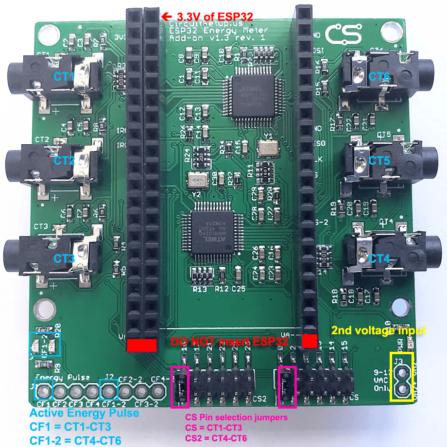
The Expandable 6 Channel ESP32 Energy Meter is made so that an ESP32 dev board can be plugged directly into the meter. See the list above for compatible ESP32 dev boards. Always insert the ESP32 with the 3V3 pin in the upper left of the meter. The bottom pins are used to connect the voltage signal (from the power plug) to add-on boards. If the ESP32 is inserted into the bottom pins it will more than likely short the ESP32.
The Expandable 6 Channel ESP32 Energy Meter uses SPI to communicate with the ESP32. Each board uses 2 CS pins.
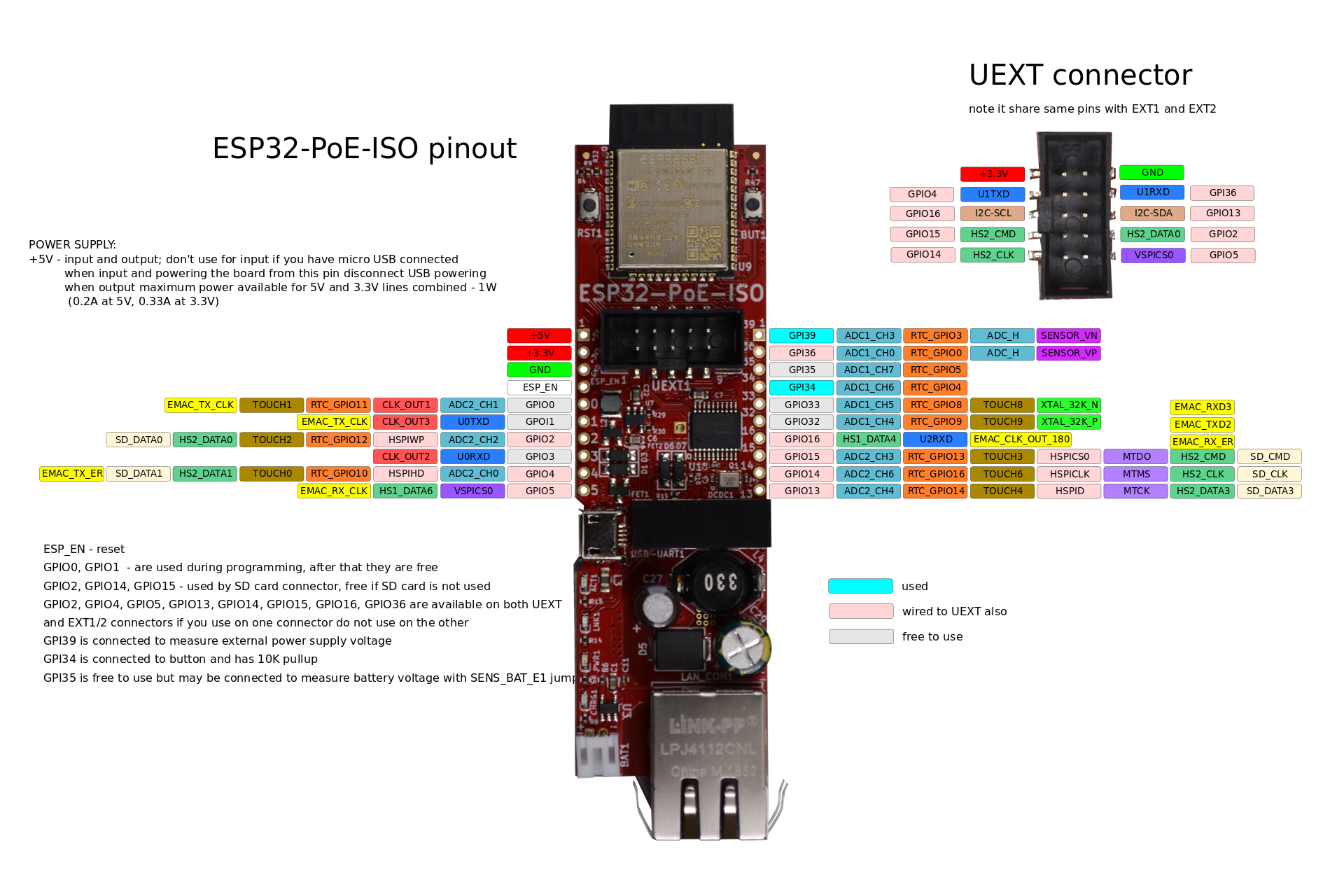
The main board uses the following SPI pins:
- CLK - 18
- MISO - 19
- MOSI - 23
- CS1 - 5 (CT1-CT3 & Voltage 1)
- CS2 - 4 (CT4-CT6 & Voltage 2)
The version of EmonESP available here has all of these pins set by default.
For examples of how to set up your config in ESPHome, see here and here.
Add-on boards (up to 6) can expand the main energy meter up to 42 current channels & 8 voltage channels. The add-on boards plug directly into the main board as seen here.
The add-on board allows the CS pin to be selected based on the jumper settings at the bottom of the board. This is so multiple add-on boards can be used - up to 6 maximum. Do NOT select more than one CS pin per bank. The CS pins can be:
- CT1-CT3 (CS):
- For v1.3 and under:
- 0
- 2 (*make sure that an on board LED is not used for IO2 on the ESP32)
- 12 (*will cause ESP32 to not boot if used)
- 13
- 14
- 15
- For v1.4 and above:
- 0
- 27
- 35 (do not use - it will not work correctly)
- 13
- 14
- 15
- For v1.4 rev1 and above:
- 35 is changed to 2 (may prevent the ESP32 from being programmed - disconnect jumper if so)
- For v1.3 and under:
- CT4-CT6 (CS2):
- 16
- 17
- 21
- 22
- 25
- 26
See here for the calibration procedure, or here for a video
- Current Transformers:
- 20A/25mA SCT-006: 11143
- 30A/1V SCT-013-030: 8650
- 50A/1V SCT-013-050: 15420
- 80A/26.6mA SCT-010: 41660
- 100A/50ma SCT-013-000: 27518
- 120A/40mA: SCT-016: 41787
- 200A/100mA SCT-024: 27518
- 200A/50mA SCT-024: 55036
- AC Transformers
- Jameco 9VAC Transformer 157041:
- For meter versions:
- v1.3 or greater: 7305
- v1.2: 42620
- For meter versions:
- Jameco 9VAC Transformer 157041:
The Expandable 6 Channel ESP32 Energy Meter uses 2 ATM90E32AS ICs. Each IC has 3 voltage channels and 3 current channels. In order for power metering data to be calculated internally, each current channel must have a reference voltage. If the voltage is out of phase with the current, then the current and power will read as negative, affecting the power factor and power calculations. If you have a split single phase or dual phase setup, the solution is to turn around the current transformer on the wire.
v1.1 of the meter used 1 of the voltage channels for each IC. This means that power and metering data would have to be calculated in software, or voltage channels would have to be mapped via changing registers on the IC to get power and metering data from CT2, CT3, CT5, CT6.
v1.2 & v1.3 have JP8-JP11 on the back of the board, that would allow all voltage channels to be connected together, which would allow power and other metering values to be calculated. Most of v1.3 came soldered together.
v1.4 removed JP8-JP11, and has voltage channels connected internally on the pcb.
For split single phase applications, dual pole circuits have 2 hot wires that total 240V (usually red and black in newer buildings). In most cases both poles are used equally, but in others there may be electronics in the applicance that use only 1 pole. There are 3 different options for measuring these circuits:
- Monitor 1 phase with 1 CT, and double the current output in software (least accurate) See details on how to do this in ESPHome here.
- Use 2 CTs to monitor each hot wire on the circuit (if you are monitoring 1 voltage, they should be in opposite directions from eachother)
- If you have enough wire, and the CT is large enough, run both hot wires through 1 CT in opposite directions
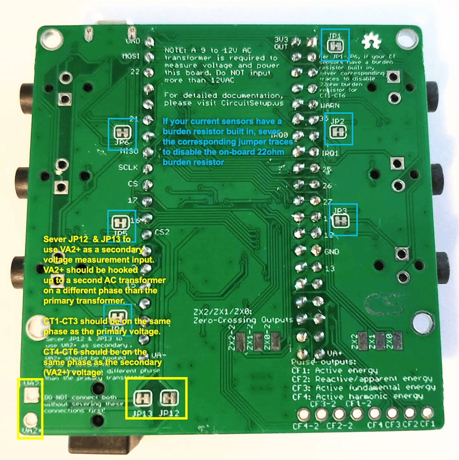
The holes labelled VA2 next to the power plug on the meter main board, and in the bottom right of the add-on board are for measuring a second voltage. To do this you must:
- Sever (with a knife) JP12 and JP13 on the back of the board for v1.3+, or JP7 for prior versions
- Use a second AC transformer, ideally one identical to the primary
- Plug in the second AC transformer to an outlet on the opposite phase to the primary
- Solder on a pin header, 3.5mm (2.54mm for v1.3 and earlier) screw connector, or DC style jack pigtail on to VA2+ & VA2- (next to the main power/voltage jack)
When voltage jumpers are severed, the voltage reference for CT4-CT6 will be from VA2. This means that current transformers for CT4-CT6 should be hooked up to circuits that are on the same phase as VA2, and CT1-CT3 should be hooked up to circuits that are in phase with the primary voltage. If a CT is not in phase with the voltage its current and power readings will be negative. If, for example, you have 4 circuits in phase with the primary, and 2 in phase with VA2, you can reverse the current transformer on the wire to put it in phase with the voltage (assuming split single phase or dual phase)
For add-on boards, the primary voltage will come from the main board. The optional secondary voltage measurement (also VA2 pins), will be in phase with CT4-CT6.
What you'll need to measure all 3 phases properly:
- 6 Channel Main Board (v1.4 and above)
- 6 Channel Add-on Board
- 3 voltage transformers - one for each phase. These can either be wall, plug-in type (if you have an outlet wired to each phase), or stand-alone transformers wired directly to breakers. They must bring down the voltage to between 9-14VAC. The first one that plugs into the main board also powers the ESP32 and electronics, so it must output at least 500mA.
- Headers soldered to the VA2 terminals on the main board and add-on board
- JP12 and JP13 severed on the main board & add-on boards Similar to the above for measuring a second voltage, once JP12 and JP13 are severed:
- CT1-CT3 on the main board, and CT1-CT3 on the add-on board will be in phase with the 1st phase
- CT4-CT6 on the main board with the 2nd phase
- CT1-CT6 on the add-on board with the 3rd phase.
The transformers should be calibrated individually for greater accuracy.
Alternately, you can use 2 add-on boards and connect 1 transformer to to each board:
- Locate the bottom most pins (i.e. those which the ESP32 does not plug into), marked "VA-" and "VA+" for each add-on board. These normally provide the voltage reference to the add-on board from the main board
- Cut these pins off
- Solder a connector, or the wires from a transformer, in the bottom right holes marked "VA2" on the add-on boards. Polarity does not matter (if you are getting negative current readings, reverse the CT on the wire)
- Do not sever JP12 and JP13
On 3-phase systems, a current transformer that's connected to a phase not in phase with the voltage reference will always result in near-zero active power and power factor.
EmonESP is used to send energy meter data to a local install of EmonCMS, or emoncms.org. Data can also be sent to a MQTT broker through this. EmonCMS has Android and IOS apps. The ESP32 sofware for EmonESP is located here, and can be flash to an ESP32 using the Arduino IDE or PlatformIO. See details on setup here.
ESPHome can be loaded on an ESP32 to seamlessly integrate energy data into Home Assistant. Energy data can then be saved in InfluxDB and displayed with Grafana. At the same time, the energy data can also be used for automations in Home Assistant.
A new feature in Home Assistant allows you to monitor electricity usage directly in Home Assistant. You can also track usage of individual devices and/or solar using the 6 channel meter!
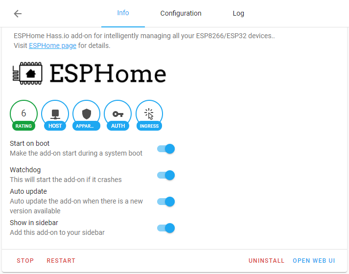
- If you have Home Assistant installed, go to Settings in the left menu, click Add-ons, then Add-on Store (bottom right blue button), Search for ESPHome - Click on Install
- Click on Open Web UI
- Click the green + circle in the bottom right to add a new node
- Fill in the name (for exmaple 'energy_meter', and device type as NodeMCU-32S or Generic ESP32
- Add your wifi details and click Submit to create the node
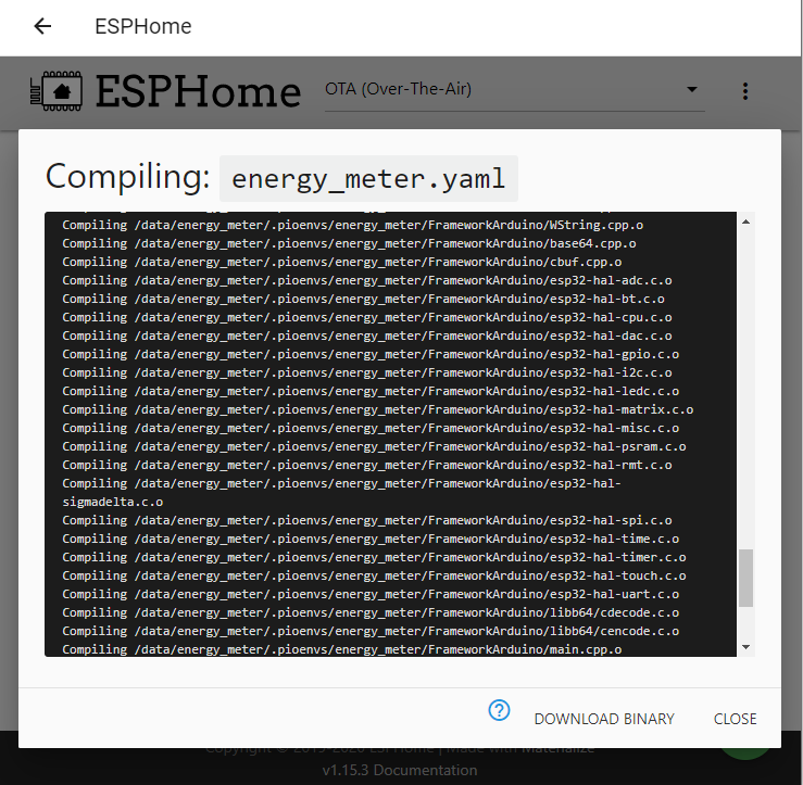
- ESPHome will compile - when it is complete click Download Binary
- Download the ESPHome flasher tool for your OS here
- Connect the ESP32 that you intend to use with your meter to your computer via USB (it does not need to be plugged into the meter at this point, but if it is, do not plug in the AC transformer yet for the meter at the same time the ESP32 is plugged into USB)
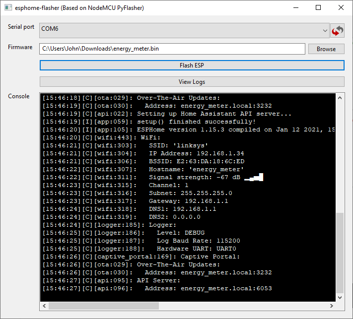
- In the ESPHome flasher, select the COM port that the ESP32 is connected to
- Select the .bin file you just downloaded and click Flash ESP (If it doesn't connect, click view logs to see what is going on - you will probably have to hold down the right Boot button on the ESP32 after clicking on Flash ESP)
- ESPHome will be loaded on the ESP32 with a basic config
- Assuming the ESP32 is close enough to the AP you want to connect to for WiFi, it should now be available in ESPHome within Home Assistant
- In Home Assistant go to Settings > Devices & Services, and click on the blue Configure for ESPHome. It should be highlighted as Discovered
- Choose an exmaple config that best suits your energy meter setup here on the ESPHome site, and here for some more advanced configurations
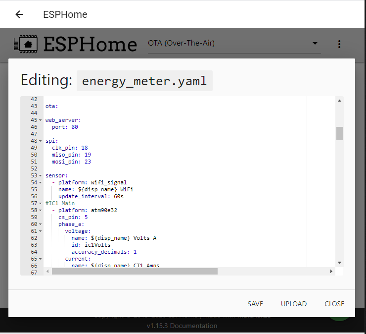
- In the Home Assistant/ESPHome Web UI, click Edit for the Energy Meter Node
- Copy/Paste the example config, change any applicable settings, like the current calibrations to the current transformers that you use, and click Save
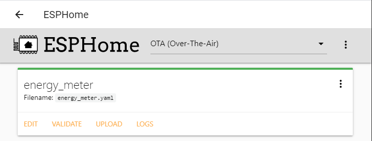
- At this point it's a good idea to close the edit dialog, and click Validate on the main screen to make sure your .yaml file is valid. Fix any errors that may come up.
- Click Upload to save your configuration to the ESP32. Note that if you have 4 or more add-on boards, you may get an error and run out of memory on your ESP32 if you have a lot of sensors. See details here.
- For greater accuracy, you can calibrate the current sensors. See here, or here for a video
- When updating values for current transformers in the ESPHome config, click Edit, then Upload
- If you don't already, install the InfluxDB add-on in Home Assistant via Settings > Add-ons > Add-on Store (bottom right blue button)
- Open the Web UI, and click on the InfluxDB Admin tab, add a database homeassistant
- Click on the Users tab (under Databases on the same screen), and create a new user homeassistant with All permissions
- Go to Settings > Add-ons > InfluxDB > Documentation (top menu) > Integrating into Home Assistant, and follow the instructions for editing your Home Assistant configuration.yaml
- Restart Home Assistant
- Data should now be available in Home Assistant and available under http://homeassistant.local:8086 or the IP of Home Assistant
To display data in the Home Assistant Energy Dashboard you must be using ESPHome v1.20.4 or higher, and have at least one total_daily_energy platform configured in your ESPHome config. time is also needed.
#Total kWh
  - platform: total_daily_energy
    name: ${disp_name} Total kWh
    power_id: totalWatts
    filters:
      - multiply: 0.001
    unit_of_measurement: kWh
time:
  - platform: sntp
    id: sntp_time
Where totalWatts is the sum of all watt calculations on the meter. See an example of this here. In the example, this was done with a lambda template.
The same can be done as above to track solar panel use and export. The current channels on the meter that are tracking solar usage must have their own lambda template calculation.
See this example for how you could set this up with the 6 Channel Meter.
To do this you must have power calulated by the meter, or a lambda template that calculates watts per circuit. Then can use a kWh platform for each of the current channels on the 6 channel energy meter. For example:
#CT1 kWh
  - platform: total_daily_energy
    name: ${disp_name} CT1 Watts Daily
    power_id: ct1Watts
    filters:
      - multiply: 0.001
    unit_of_measurement: kWh
ct1Watts references the id of the watt calculation. In the example config, this is:
      power:
        name: ${disp_name} CT1 Watts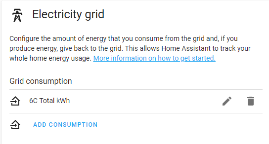
id: ct1Watts- Go to Configuration > Energy
- For total energy, click Add Consumption under Electricity grid
- The name of the total_daily_energy platform, like 6C Total kWh, should be available to choose
- You can also set a static cost per kWh or choose an entity that tracks the cost of your electricity
- For Individual devices chose the name of the individual circuits, like 6C CT1 Watts Daily
- If monitoring your Solar Panels with a 6 channel meter, you can also set this here, but it will not register unless energy is being consumed by your house or flowing out to the grid.
Q: I am getting a low reading, or nothing at all for one CT - what is wrong?
A: Sometimes the jack for the CT is a bit stiff, and you may need to push in the CT connector into the board jack until it clicks. If it is definitely all the way in, it's possible the connector or somewhere else has a loose connection, and we will replace the meter for free.
Q: Does the 6 channel energy meter work in my country?
A: Yes! There is a setting to set the meter to 50Hz or 60Hz power. You will need to purchase an AC transformer that brings down the voltage to between 9-12V AC. Transformers for the US are for sale in the circuitsetup.us store.
Q: I'm getting a negative value on one current channel. What is going on?
A: This usually means that the CT is on the wire backwords - just turn it around!
Q: I'm getting a small negative value when there is no load at all, but a positive value otherwise. What is going on?
A: This is caused by variances in resistors and current transformers. You can either calibrate the current transformers to the meter, or add this lambda section to only allow positive values for a current channel:
  - platform: template
    name: ${disp_name} CT1 Watts Positive
    id: ct1WattsPositive
    lambda: |-
      if (id(ct1Watts).state < 0) {
        return 0;
      } else {
        return id(ct1Watts).state ;
      }
    accuracy_decimals: 2
    unit_of_measurement: W
    icon: "mdi:flash-circle"
    update_interval: ${update_time}
Then for your total watts calculation, use ct1WattsPositive
Q: The CT wires are not long enough. Can I extend them?
A: Yes, you absolutely can! Something like a headphone extension or even an ethernet wire can be used (if you don't mind doing some wiring). It is recommended to calibrate the CTs after adding any particularly long entension.
Q: Can I use this CT with the 6 channel meter?
A: More than likely, yes! As long as the output is rated at less than 720mV RMS, or 33mA.
Q: Can I use SCT-024 200A CTs with the 6 channel meter?
A: If you need to measure up to 200A, then this is not recommended. At 200A, our newest SCT-024's will output 50mA. That means, the max you should measure with the SCT-024 plugged into the 6 channel meter is 132A. In a residential setting with 200A service, it is highly unlickly that you will use more than 132A per phase sustained. In fact, unless you have your own dedicated transformer, and a very large house, it is impossible.
Q: How do I know if my CT has a burden resistor?
A: There is a built in burden resistor if the output is rated in volts. In this case the corresponding jumper on the rear of the meter should be severed.
Q: When using more than 3 add-on boards, ESPHome does not work.
A: ESPHome will run out of stack memory after using more than 15 sensors, or so. You will have to increase the stack memory size before compiling. See details here.
UPDATE: You can replace the esphome: definition in your ESPHome config to solve this issue with the following:
esphome:
  name: 6chan_energy_meter
  platformio_options:
    build_flags:
      - -DCONFIG_ARDUINO_LOOP_STACK_SIZE=32768

esp32:
  board: nodemcu-32s
  variant: esp32
  framework:
    type: arduino
    version: 2.0.2
    source: https://github.com/espressif/arduino-esp32.git#2.0.2
    platform_version: https://github.com/platformio/platform-espressif32.git#feature/arduino-upstream


