Code Monkey home page Code Monkey logo

hoverboard-firmware-hack's Introduction

hoverboard-firmware-hack

This repo contains open source firmware for generic Hoverboard Mainboards. The firmware you can find here allows you to use your Hoverboard Hardware (like the Mainboard, Motors and Battery) for cool projects like driving armchairs, person-tracking transportation robots and every other application you can imagine that requires controlling the Motors.

If you want an overview of what you can do with this firmware, here is a ~40min video of a talk about this project: https://media.ccc.de/v/gpn18-95-howto-moving-objects


Build Instructions

Here are detailed build instructions for some finished projects. If possible, a prebuild firmware release is available for these usecases, so you don't need to compile the firmware yourself

TranspOtter: https://github.com/lucysrausch/hoverboard-firmware-hack/wiki/Build-Instruction:-TranspOtter


Hardware

otter

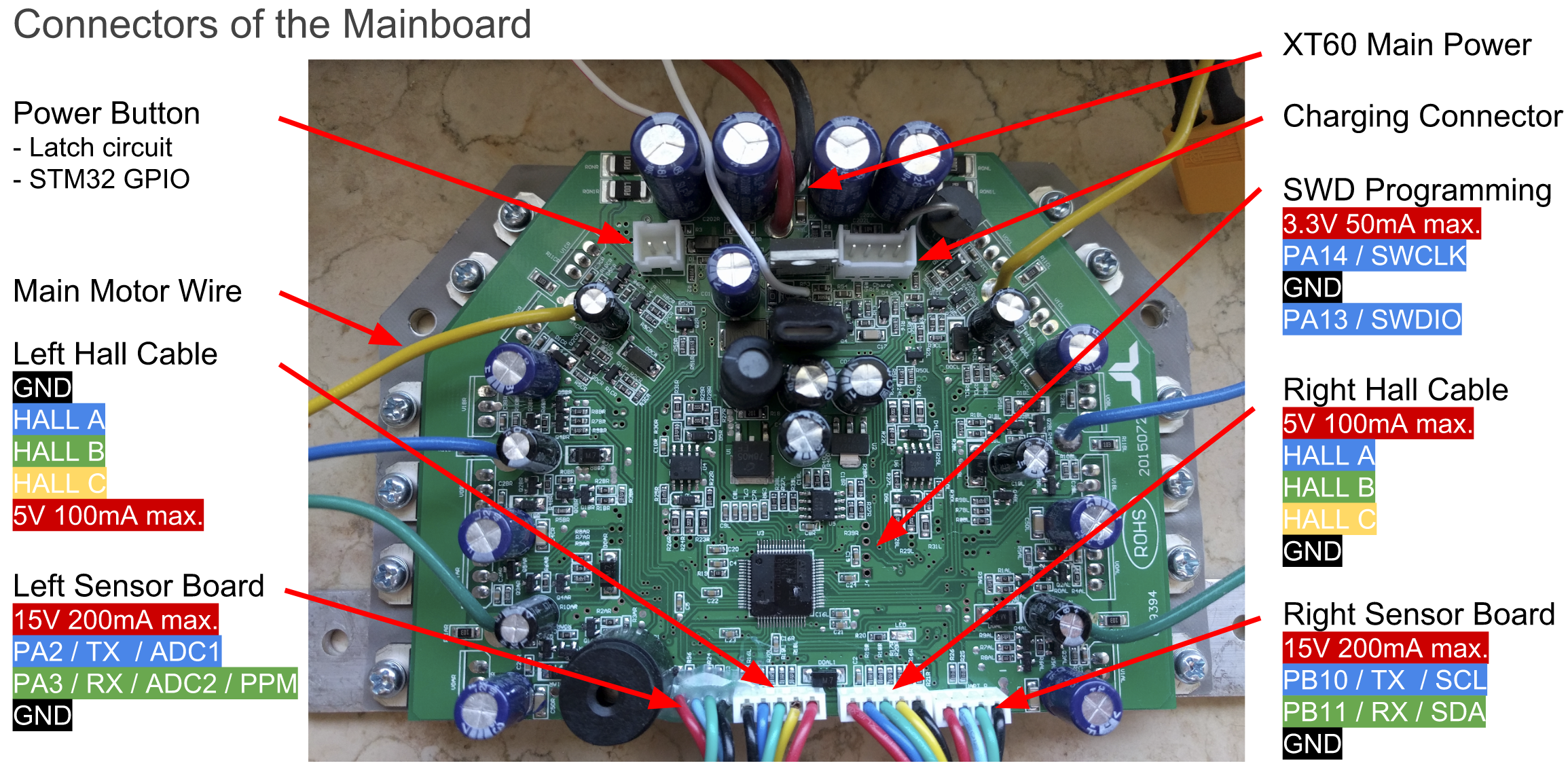
The original Hardware supports two 4-pin cables that originally were connected to the two sensor boards. They break out GND, 12/15V and USART2&3 of the Hoverboard mainboard. Both USART2 & 3 can be used for UART and I2C, PA2&3 can be used as 12bit ADCs.

The reverse-engineered schematics of the mainboard can be found here: http://vocke.tv/lib/exe/fetch.php?media=20150722_hoverboard_sch.pdf


Flashing

To build the firmware, just type "make". Make sure you have specified your gcc-arm-none-eabi binary location in the Makefile ("PREFIX = ...") (version 7 works, there is a version that does not!) (if the ons in linux repos do not work, use the official version: https://developer.arm.com/open-source/gnu-toolchain/gnu-rm/downloads). Right to the STM32, there is a debugging header with GND, 3V3, SWDIO and SWCLK. Connect GND, SWDIO and SWCLK to your SWD programmer, like the ST-Link found on many STM devboards.

Do not power the mainboard from the 3.3V of your programmer! This has already killed multiple mainboards.

Make sure you hold the powerbutton or connect a jumper to the power button pins while flashing the firmware, as the STM might release the power latch and switches itself off during flashing. Battery > 36V have to be connected while flashing.

To flash the STM32, use the ST-Flash utility (https://github.com/texane/stlink).

If you never flashed your mainboard before, the STM is probably locked. To unlock the flash, use the following OpenOCD command:

openocd -f interface/stlink-v2.cfg -f target/stm32f1x.cfg -c init -c "reset halt" -c "stm32f1x unlock 0"

If that does not work:

openocd -f interface/stlink-v2.cfg -f target/stm32f1x.cfg -c init -c "reset halt" -c "mww 0x40022004 0x45670123" -c "mww 0x40022004 0xCDEF89AB" -c "mww 0x40022008 0x45670123" -c "mww 0x40022008 0xCDEF89AB" -c "mww 0x40022010 0x220" -c "mww 0x40022010 0x260" -c "sleep 100" -c "mww 0x40022010 0x230" -c "mwh 0x1ffff800 0x5AA5" -c "sleep 1000" -c "mww 0x40022010 0x2220" -c "sleep 100" -c "mdw 0x40022010" -c "mdw 0x4002201c" -c "mdw 0x1ffff800" -c targets -c "halt" -c "stm32f1x unlock 0"
openocd -f interface/stlink-v2.cfg -f target/stm32f1x.cfg -c init -c "reset halt" -c "mww 0x40022004 0x45670123" -c "mww 0x40022004 0xCDEF89AB" -c "mww 0x40022008 0x45670123" -c "mww 0x40022008 0xCDEF89AB" -c targets -c "halt" -c "stm32f1x unlock 0"

Or use the Windows ST-Link utility.

Then you can simply flash the firmware:

st-flash --reset write build/hover.bin 0x8000000

or

openocd -f interface/stlink-v2.cfg -f target/stm32f1x.cfg -c flash "write_image erase build/hover.bin 0x8000000"

Troubleshooting

First, check that power is connected and voltage is >36V while flashing. If the board draws more than 100mA in idle, it's probably broken.

If the motors do something, but don't rotate smooth and quietly, try to use an alternative phase mapping. Usually, color-correct mapping (blue to blue, green to green, yellow to yellow) works fine. However, some hoverboards have a different layout then others, and this might be the reason your motor isn't spinning.

Nunchuck not working: Use the right one of the 2 types of nunchucks. Use i2c pullups.

Nunchuck or PPM working bad: The i2c bus and PPM signal are very sensitive to emv distortions of the motor controller. They get stronger the faster you are. Keep cables short, use shielded cable, use ferrits, stabilize voltage in nunchuck or reviever, add i2c pullups. To many errors leads to very high accelerations which triggers the protection board within the battery to shut everything down.

Most robust way for input is to use the ADC and potis. It works well even on 1m unshielded cable. Solder ~100k Ohm resistors between ADC-inputs and gnd directly on the mainboard. Use potis as pullups to 3.3V.


Examples and links

Have a look at the config.h in the Inc directory. That's where you configure to firmware to match your project. Currently supported: Wii Nunchuck, analog potentiometer and PPM-Sum signal from a RC remote. A good example of control via UART, eg. from an Arduino or raspberryPi, can be found here: https://github.com/p-h-a-i-l/hoverboard-firmware-hack

If you need additional features like a boost button, have a look at the while(1) loop in the main.c

Hoverboardhack for AT32F403RCT6 based mainboards

Hoverboardhack for split mainboards

Online Compiler

Additional Hardware

Projects based on it

  • Bidirectional UART communication with Arduino example code
  • bobbycar-optimized firmware based on this one with driving modes, acceleration ramps and some other features
  • wheel chair controlled with a joystick or using a CC2650 sensortag to control it over bluetooth with pitch/roll.
  • TranspOtterNG TranspOtter is an open source semi self driving transportation platform based on hoverboard hardware
  • BiPropellant - fork which focusses on reliable machine control, but also retains HoverBoard functionality if desired.

hoverboard-firmware-hack's People

Contributors

blubbi321 avatar btsimonh avatar crinq avatar jana-marie avatar larsmm avatar leodj avatar p-h-a-i-l avatar rene-dev avatar tobleminer avatar trilader avatar

Stargazers

 avatar  avatar  avatar  avatar  avatar  avatar  avatar  avatar  avatar  avatar  avatar  avatar  avatar  avatar  avatar  avatar  avatar  avatar  avatar  avatar  avatar  avatar  avatar  avatar  avatar  avatar  avatar  avatar  avatar  avatar  avatar  avatar  avatar  avatar  avatar  avatar  avatar  avatar  avatar  avatar  avatar  avatar  avatar  avatar  avatar  avatar  avatar  avatar  avatar  avatar  avatar  avatar  avatar  avatar  avatar  avatar  avatar  avatar  avatar  avatar  avatar  avatar  avatar  avatar  avatar  avatar  avatar  avatar  avatar  avatar  avatar  avatar  avatar  avatar  avatar  avatar  avatar  avatar  avatar  avatar  avatar  avatar  avatar  avatar  avatar  avatar  avatar  avatar  avatar  avatar  avatar  avatar  avatar  avatar  avatar  avatar  avatar  avatar  avatar  avatar

Watchers

 avatar  avatar  avatar  avatar  avatar  avatar  avatar  avatar  avatar  avatar  avatar  avatar  avatar  avatar  avatar  avatar  avatar  avatar  avatar  avatar  avatar  avatar  avatar  avatar  avatar  avatar  avatar  avatar  avatar  avatar  avatar  avatar  avatar  avatar  avatar  avatar  avatar  avatar  avatar  avatar  avatar  avatar  avatar  avatar  avatar  avatar  avatar  avatar  avatar  avatar  avatar  avatar  avatar  avatar  avatar  avatar  avatar  avatar  avatar  avatar  avatar  avatar  avatar  avatar  avatar  avatar  avatar  avatar  avatar  avatar  avatar  avatar  avatar  avatar  avatar  avatar  avatar  avatar  avatar  avatar  avatar  avatar  avatar  avatar  avatar  avatar

hoverboard-firmware-hack's Issues

[Feature request] Mirror motor speeds

It was pretty easy to add a "* -1" to one of the motor speeds in the files, but would still be useful for some people to have a setting right in the config that makes both motors go in the same direction (for a scooter with both wheels mounted from the same side for example).

Mainboard blew up

Hi there,

I did flash your code to my board successfully, but it blew up once I connected it.

image

I don't know what was the problem, do you think I could replace those components?

Motor disabled when braking

Hey,
I am using a single motor on a scooter, currently controlled by the wii nunchuck.

  • With no weight on the vehicle everything works fine.

  • If I am driving with atleast 50% speed, I can slowly decrease the speed (slowly moving the joystick back to the neutral position), which will successfully brake down and stop the vehicle. But ... if I brake to fast, the motor will just shut down and I'll have to restart the mainboard.

Is there any way around this? Is it this line maybe?

#define TIMEOUT 5 //number of wrong / missing commands before emergency off

Expected Mainboard Behavior During Connection

Im trying to flash my first board with the firmware. My issue is that it is a used board and I dont know whether its working or not because I have never seen a working one / dont know that its working for sure ..

What I did:

  • connect SWCLK, GND, SWDIO as described in the readme to the stlink CN4 on a nucleo board (and removed both jumpers from CN2
  • jumper to the on/off button of the board
  • disconnected all additional hardware from the mainboard (no sensor boards, no motors, etc)
  • used a charger as power supply as I dont have a > 36V power source

What I observe:

  • current drawn from the power supply ~2mA (0mA when taking off the jumper), voltage at 42V
  • no connection possible to the target using the st link utility (usb connection error)

Can anybody tell from these observations whether the mainboard is dead? Or am I missing anything completely?

LCD code not working.

Hi,
I have tried to enable the LCD code by de-commenting the IFDEF flag in config.h
#define DEBUG_I2C_LCD
After this the code does not compile.
I am at a bit of a loss as there are a lot of HAL calls involved with the LCD of which I am unfamiliar.

The compile error I get is this.

Src/main.c:143:5: error: 'lcd' undeclared (first use in this function)
lcd.pcf8574.PCF_I2C_ADDRESS = 0x27;
^~~
Src/main.c:143:5: note: each undeclared identifier is reported only once for each function it appears in
Src/main.c:146:29: error: 'NUMBER_OF_LINES_2' undeclared (first use in this function)
lcd.NUMBER_OF_LINES = NUMBER_OF_LINES_2;
^~~~~~~~~~~~~~~~~
Src/main.c:147:18: error: 'TYPE0' undeclared (first use in this function)
lcd.type = TYPE0;
^~~~~
Src/main.c:149:10: warning: implicit declaration of function 'LCD_Init'; did you mean 'HAL_Init'? [-Wimplicit-function-declaration]
if(LCD_Init(&lcd)!=LCD_OK){
^~~~~~~~
HAL_Init
Src/main.c:149:26: error: 'LCD_OK' undeclared (first use in this function); did you mean 'HAL_OK'?
if(LCD_Init(&lcd)!=LCD_OK){

Schematic and FOC motor control??

Hi.

Can you guys point me to a schematic in case anyone already go it??

Can the hardware do FOC? For what I could understand from your code, there are 2 phase currents for each motor, right?

Does the motors run as much silent with your firmware as with original firmware?

Please make a firmware for stm32, which will communicate with the ROS via the rosserial , like in turtlebot3

Please make a firmware for stm32, which will communicate with the ROS via the rosserial, like here in turtlebot3 http://emanual.robotis.com/docs/en/platform/turtlebot3/opencr_setup/#opencr-setup .
About rosserial and the protocol of communication between the openCR and the raspberry pi can be read here http://community.robotsource.org/t/download-the-ros-robot-programming-book-for-free/51
It is necessary that the data on the odom and imu arrive correctly.

Firmware flash

First Great job with project and video is awesome.
My issue is putting firmware together and flashing, anyway you can detail that process out for an old newbie?
Also I have two hover boards that only use two boards so have you seen those and do you have a hack for those?

Thanks so much

Speed and Efficiency Problems

I have two identical Hoverboards (same Mainboard). I use one for this project, the other still runs the original Firmware.
I build two kids cars with conversion sets like this: https://www.youtube.com/watch?v=dKItIbBd3x8
I use the original batteries (10s), current is limited to 15A per Motor. Input device is a nunchuck.

The Board running the hoverboard-firmware-hack gets hotter, drains the battery faster and is slower
than the cart with the original firmware.
What could be the Problem here? I read about block commutation, sinusodial control and FOC, but without the tools to measure the actual signals i dont know what exactly needs to be changed.
My main concern are the Motors, wich get hot quite fast. Whe spinning freely, they stay cool.
Did anyone observe the same Problems?

Discussion on possible control pins, other than USARTs

I have completed my implementation of reception from the two original sensor boards, but unfortunately this means that the two USARTs are now in use... I can get diagnostic data via output to one of the ports (which is ignored by the sensor board), but now want bi-directional comms with the main board for the next steps.

I'm using a YST board, which has an un-populated IC site with connections to PB3/PB4; these can be SPI1_SCK/SPI1_MISO. It seems like SPI could be used as a communications mechanism.

I've just noticed that it also breaks out pins 28 (PB2), 40 (PC9), 44 (PA11) into a very convenient location.

With the limited number of available IO ports, a single wire mechanism seems in order.

I am not familiar with SPI; does anyone have comments on this? Can it be used without SPI1_MOSI and SPI1_NSS? Is SPI an easy implementation on, for example, an ESP8266?

Another option is a 1-wire slave device, e.g. emulating a 1-wire eeprom would allow for a slow but flexible communications mechanism, and is easily supported by external hardware. This could even be used on PB2 (LED on the diagram in this repo).

Another option is bit-banged serial, using two pins...

So, comments please. Do other boards have 'easy' ways to connect to these pins (PB3/4)? Would it be best to go for the bit-banged approach (1-wire or serial), just so that users can have 'free choice' of the pins they use?

Question ?

Hello , i am now on a project to improve the standart hoverboard to use on y company , the thing s that make me so confuse are, the sensor output, i wonder what is the sensor output ? maybe you can help me, thnaks...

sorry for bad english.

Explanation of the bldc.c-routine (Trapezoidal control 3-phase BLDC motors using hall sensors)

Hey guys,

I found an interesting article in my research of understanding what is done in the bldc.c-Routine to control the motor. If you want to unterstand the trapezoidal control of the 3-phase BLDC motors using hall sensors this might help you:

https://e2e.ti.com/blogs_/b/motordrivecontrol/archive/2013/11/08/generate-your-own-commutation-table-trapezoidal-control-3-phase-bldc-motors-using-hall-sensors

https://e2e.ti.com/blogs_/b/motordrivecontrol/archive/2013/12/20/generate-your-own-commutation-table-part-2

Especially look at part 2 where you find the explanation how the angle between the stator magnetic field and the rotor flux, could be set to 90° and the matching pwm-setting in the bldc.c-routine. Attention should be paid to the fact that 50% pulse duty factor per phase means Aoff, Boff and Coff. That wasnt clear to me in the beginning.

Hope I could help you to understand faster than I did.

Florian

how to read serial with USB-UART adapter and arduino

Hi

I was able to flash the main board. after i flash the board, when i turn on the hoverboard the wheels start rotating but when i connect the USB-UART adapter to Gnd. PA2 & PA3 to get commands and i dont get any output on the serial monitor. what im doing wrong? i will like to control it with arduino. any help will be appreciate it

thank you

List of supported boards?

I know its hard for chinese hardware but it would be great if we could assemble a list of supported devices to avoid people blowing up boards like here #32 ..

More specifically I am wondering whether I should feel brave enough to flash the firmware on this board:
grafik

Any idea if this is supported hardware? Seems to be a fairly recent design according to the date printed on it.

[FeatureRequest] PID position control

Hello,
Is it possible to implement PID in the motor controller to obtain more accurate speed and position control instead of speed?
I can help you on some parts but I don't know how to do, especially for the position.

Thank you

Actual RPM

Would it be possible to get an actual motor RPMs using hall sensors and have this info put into debug UART? If this is already possible, could you put me on the way, because I'm not much of a coder.

Beginner friendly way to control the mainboard via I2C?

Hey, the workshop was awesome. Nunchuk control works perfectly!

I would like to use an Arduino to control the speeds (no steering needed - wheels just move in one direction basically - something like motSpeed(x); would work as a function in the Arduino IDE). I believe, the easiest and most logical way would be I2C.

Edit: This is solved. See my first comment for the solution.

As far as I understand this with my very limited knowledge in C, I would need to add something like
#define CONTROL_ARDUINO
in the config.h. To tell it which control method to use.

Then in the control.c, I would need to write a function that receives the data that is being sent from the Arduino.

  • Can I just read it directly or do I also need to do an init as it's done with a Nunchuk?
  • How exactly does the board "want" to receive the data?
    Could I have some words about frquencies, handshakes etc. so I can do research and build a function like this an arduino sketch that would fit those needs?

Lastly I would need to edit the while(1) loop in the main.c. As far as i can tell. cmd1 and cmd2 are the values for speed and steering.

  • Which range of numbers do they normaly accept? For example would cmd2 = 100; already do something?
    #ifdef CONTROL_Arduino
      Arduino_Read();
      cmd2 = CLAMP((arduino_data[1] - 128) * 8, -1000, 1000); // y - axis
    #endif

(This is more or less pseudo-code. That calculation probably isn't needed).

I am trying to get this done, but I am lacking the knowledge here. Any help, hints in the right directions etc. are greatly appreciated! :)

Nunchuck reinitialization

Hi,
Im still trying to find ways to use the nunchuck. Still experiencing problems when braking as described here: #9.

Environment:
Original Nunchuck, tested black and white, whith and without extra caps and TVS diodes on all lines.

During testing I noticed, that the nunchuck reinitialization does not seem to work. Physical reconnecting of the nunchuck always requires a reboot.
-phail

The board wouldn't completely turn off

The board with default git code would not turn off. After the power button is pressed the motor is stopped, but the LED remains. From this point the board does not respond to anything. Needs power recycling.

The issue seemed to go away after I changed DELAY_IN_MAIN_LOOP to 5 in config.h:9
(even the comment indicates that the default value is 5, but git code has the value of 2).

Did anyone look at the hoverboards with two identical separate controllers?

I have a hoverboard with two separate controllers (image below).

Did you consider this design of controller at any point?
They seem to produce a 200kbaud output (not fully analysed yet, so not sure if they can be controlled).
The firmware is protected; can't be extracted. I am on the lookout for a suitable binary file if anyone has one - so far nothing has come up in google.
I have done a basic outline of the MCU connections; if anyone is interested, I could write this up.

MCU is GD32F103C8T6, sensor is marked Mb81 (?) but appears to match an MCU-6050 pinout.

20180729_085227

Beginner question.

Hi. I am new to STM32. Which toolchain will work with your code (update: I found in one of the files it was created with System Workbench for STM32...)? https://gnu-mcu-eclipse.github.io/ ? (Any small toolchain? - don't want to put too much garbage on my Windows just for this project). Another question is how to backup original firmware (command for st-link)?
Tnx Rok

Motor issues - Erratic / Uncontrollable Wheel / Power Lock Out

(firstly - love the project, thanks to all contributors).
I have some unexpected motor issues, all relating to motor operation.

Environment: Firmware flashed via Ubuntu using described flash method. My hoverboard appears to be the same PCB as the PCB shown on the main project page here - markings on my PCB are 679394 ROHS 20150722

I have flashed with a variety of combinations, toggling define DEBUG_SERIAL_USART3 and define DEBUG_SERIAL_USART2 and have tired multiple combinations of uncommenting various CONTROL and DRIVING BEHAVIOR settings as per the config.h file.

Issues:

Note: The below issues have been observed while the Nunchuck is directly connected to the Hoverbaord (via jumper leads), and also when the Nunchuck is connected to the Breakout PCB. I understand there is EM interference from the motors, however this seems like a firmware issue, not a control/interference issue.

  1. Nunchuck - uncontrollable LEFT WHEEL: While the hoverboard is placed upside down (ie wheels are freely spinning in the air), when powered on the Nunchuck will correctly control the motors for a few seconds, then the RIGHT WHEEL will stop and the LEFT WHEEL will go into full throttle mode and not stop. Both wheels are now totally unresponsive to the Nunchuck control and the only way to stop the wheel is to turn the power off by pressing the power button.

  2. Nunchuck - Unit lunges erratically, then stops: While the hoverboard is placed correctly on the ground (ie wheels are in contact with the ground and there is a load/person weight on the Hoverboard), when powered on the Nunchuck will correctly control the motors for LESS THEN 1 SECOND and then the hoverboard will either lunge forward or backwards for another second and then become unresponsive, the motors will shut down and require a restart to become functional again.

  3. Unit unable to turn off: - This has only occurred once but was quite a serious issue. The unit was turned on, Nunchuck connected via cable to the Hoverboard, the wheels were on the ground and a person was on the hoverboard. The issue as per no. 2 above occurred (power on, control via Nunchuck for few seconds, unit lunged forward) however in this case the unit kept supplying power to one wheel, and the power button was completely unresponsive. The wheel started getting hotter and hotter, it couldn't freely spin (it's like it was being supplied power from all directions). The only solution was to unscrew the unit and disconnect the butter connection.

Thanks for your help in finding a solution - and again thanks for the project!

program sequence

Hi, im probably in the wrong location to post it, but dont know where else to post it.
So could someone help me get in the right direction?
I try to programm the mainboard with an raspberrypi zero w and this tutorial https://learn.adafruit.com/programming-microcontrollers-using-openocd-on-raspberry-pi/compiling-openocd
but im not sure if i should see some Serial data from the hoverboard-mainboard by default or if i have to unlock it first.
And also im not sure how to unlock it. I got this message
Open On-Chip Debugger 0.10.0+dev-00546-g1afec4f5 (2018-10-04-22:55)
Licensed under GNU GPL v2
For bug reports, read
http://openocd.org/doc/doxygen/bugs.html
BCM2835 GPIO config: tck = 11, tms = 25, tdi = 10, tdo = 9
BCM2835 GPIO nums: swclk = 11, swdio = 25
Info : auto-selecting first available session transport "jtag". To override use 'transport select '.
adapter speed: 1000 kHz
adapter_nsrst_delay: 100
jtag_ntrst_delay: 100
none separate
cortex_m reset_config sysresetreq
Info : BCM2835 GPIO JTAG/SWD bitbang driver
Info : JTAG and SWD modes enabled
open: Permission denied

Also i used the command from the readme, but shouldnt the unlock command contain something to make ocd communicate via SWD?
Sorry for these question. But i would love to have a better understanding of it.
Hope anybody can help me :) THX

Motors shaking when controlling from UART

I'm currently controlling the motors via uart2/3 (adapted code to work with either of those). In general, this works properly: speed commands are read correctly. However, sometimes, after startup the motors start shaking heavily. I don't believe the sending part goes wrong.

My current hypothesis is as follows. The shaking either happens continuously, or not at all. So, it is not happening because of inaccurate data (missed bits/bytes). Four bytes are sent as command. However, if the byte that is read is not the first one that was sent, the bytes are read shifted. E.g. normally speed least significant byte is read correctly. However, now speed lsb is read as speed msb; lsb is noisy, and so is motor speed.

Could this be correct?

Dont get the nunchuk control working

hello,
i dont get the nunchuk control working, i tried the the ADC control and that one is working.
i have tried both connectors, on two boards. nothing, and of cause i tried the nunchuk on an arduino: it works. i connected it to the board with 3k3 pullup on scl and sda...

Can someone help/ give tips?

Erratic motors

Hi. Does anyone have an idea why my motors start shaking like crazy when the speedL and speedR reach 390? I haven't tried negative values of their range -1000 to +1000.
I use the code below:

	if ((speedL < lastSpeedL + 50 && speedL > lastSpeedL - 50) && (speedR < lastSpeedR + 50 && speedR > lastSpeedR - 50) && timeout < TIMEOUT) {
			if (button1 && !button2) {
				LEFT_TIM->BDTR &= ~TIM_BDTR_MOE;  //disable left
				RIGHT_TIM->BDTR |= TIM_BDTR_MOE;  //enable right
				pwml = 0; //pwml = -speedL;
				pwmr = speedR;
			}`
			if (!button1 && !button2) {
				LEFT_TIM->BDTR |= TIM_BDTR_MOE;   //enable left
				RIGHT_TIM->BDTR |= TIM_BDTR_MOE;  //enable right
				pwml = -speedL;
				pwmr = speedR;
			}`
			if (!button1 && button2) {
				LEFT_TIM->BDTR |= TIM_BDTR_MOE;   //enable left
				RIGHT_TIM->BDTR &= ~TIM_BDTR_MOE; //disable right
				pwml = -speedL;
				pwmr = 0; //pwmr = speedR;
			}}

and DO NOT USE the original code:

	// ####### SET OUTPUTS #######
	if ((speedL < lastSpeedL + 50 && speedL > lastSpeedL - 50) && (speedR < lastSpeedR + 50 && speedR > lastSpeedR - 50) && timeout < TIMEOUT) {
	#ifdef INVERT_R_DIRECTION
	  pwmr = speedR;
	#else
	  pwmr = -speedR;
	#endif
	#ifdef INVERT_L_DIRECTION
	  pwml = -speedL;
	#else
	  pwml = speedL;
	#endif
	}

So, if I:

  1. Disable right motor (button1 = 0 and button2 = 1) => left motor can go up to speedL = 1000 and right motor rests.
  2. Disable left motor (button1 = 1 and button2 = 0) => right motor can go up to speedR = 1000, but left motor starts spinning too at speedR = speedL = 700 but pwml = 0; (not pwml = -speedL;) ????
  3. This is for the first question in this post. In this case I am in the middle IF statement (ie button1 = 0 and button2 = 0). I see erratic shaking of the motors (as believe it's right motor, but hard to tell)...

I use:
#define FILTER 0.1 // lower value == softer filter. do not use values <0.01, you will get float precision issues.
#define SPEED_COEFFICIENT 1.0 // higher value == stronger. 0.0 to 1.0
#define STEER_COEFFICIENT 0.0 // higher value == stronger. if you do not want any steering, set it to 0.0; 0.0 to 1.0
...so no STEERING, CMD2 = SPEED = speedL = speedR in range 0-1000.

Thanks for any help.

New style board; poweroff not working

Hi All,
I'm applying this to a YST-6.5"-10"-PCBA-10 board.

The original firmware loads, as does a version I built with platform.io.

However, it only works after a full power off. A button-press power off stops the motors, and then after a period starts to issue short bleeps (no power down sequence bleep as the code hints at).

Anyone else had this kind of issue?

s

Noise and vibration problem

Hi! Has anyone seen the issue with loud noise and vibration from both motors, varying with RPM? The original firmware doesn't have this issue.
The motors start up very smooth, then as they pick up revs (from speed or steer value 300 or so) the whine gets louder and louder. It's not the PWM whine, it has much lower frequency, and if I touch the frame I can feel it vibrating. Then as it gets to full speed, it gets quieter, but not much.

I'm controlling it via UART.

What software do you guys use!??

First of all, thank you guys for your work!

I am new to embedded and I was wondering what software you guys use to program STM32.

I tried to use Atollic TrueSTUDIO but I am getting thousands of errors from the original code which I am having hard time to resolve.

However, I successfully flashed/unlocked my board using ST-Link Utility with the hex file that you guys provided.

Thanks in advance!!

Wrong comment about IRQ frequency

this comment by @TomTinkering is wrong:
https://github.com/NiklasFauth/hoverboard-firmware-hack/blob/057407ae248c5eafa0e200938103e7880ab86253/Src/bldc.c#L146-L148
the irq is executed at 16 kHz, not 100. The ADC is synced to the timer trigger out:
https://github.com/NiklasFauth/hoverboard-firmware-hack/blob/057407ae248c5eafa0e200938103e7880ab86253/Src/setup.c#L461
and trigger out is fired on timer update:
https://github.com/NiklasFauth/hoverboard-firmware-hack/blob/057407ae248c5eafa0e200938103e7880ab86253/Src/setup.c#L401
all explained here:
https://github.com/NiklasFauth/hoverboard-firmware-hack/blob/057407ae248c5eafa0e200938103e7880ab86253/Src/setup.c#L23-L26

The ADC has to be synced to the pwm, and sample while the low fets are on, otherwise you cant measure the current, and all your other measurements will be noisy.

building in platform.io

Hi All,
I've just spent a couple of hours getting this to build in Platform.io. It now produces a .bin and .elf file

The modifications are here:
https://github.com/btsimonh/hoverboard-firmware-hack/tree/platformio

The output has not been tested on a board yet (I will be a week or so of analysis of existing serial first, then modify for GM32 CPU), so I won't issue a pull request until I'm more sure it will work.
The .bin file does seem a little larger than the original (~33k, compared to the hex file of ~33k, so about double the size?)

There is one code change, described in the readme.md in the platformio folder.

If someone wants to try it, and confirm, I have included a .bin file.

Use of mainboard photo with connectors on YT video.

Hi Niklas.
I make videos for youtube and would like to know if I can use your image on the main page (https://raw.githubusercontent.com/NiklasFauth/hoverboard-firmware-hack/master/pinout.png) in one (or more) of my videos? It is a video of making a hoverbike from hoverboard with your source code and my little contribution in Pull requests (hand throttle on ADC). I plan to use the photo, if you allow, and a link to your github page.
My channel: https://www.youtube.com/channel/UCIOIhhPirDJH8LB0azJmd8w
And where are you from? Germany, Austria, Swiss?
So, can I use it?
Rok

Wheels getting "stuck"? Board shutting down

Hey,
it happened a few times, that the wheel suddenly stopped while going full speed. This doesnt feel like the slowing down when releasing a nunchuk joystick to neutral, more like as if they would stop instantly. In the same moment, the mainboard shuts down and wont turn back on until the battery has been disconnected and reconnected.

I am currently using a nunchuk and my config's amp limit is set to 25.

Is this a short somewhere? A broken battery?

Unresponsive after poweron

I have two hoverboard both of which flash without issue. When I connect the battery and press the power button the boards appear to power on successfully and play the power up tone. However they both then become unresponsive and the power button will not shut them down. I have to disconnect the battery to power them down. Does anyone have any ideas what this could be?

Board halting if speed is close to 0

I have everything else working, communication, motors, all the good stuff. I have one problem though, in that if I go from -100 to 100 speed, the motors will stop and the board will become unresponsive until restarted. If I'm running it on PPM, 1400 will reverse, 1600 will forward, but going from one to the other doesn't happen. Setting a value anywhere between 1450 and 1550, or close to -50 and 50 speed, including 0, will cause the motors to stop and the board will become unresponsive. I've tried changing current limit, batteries, bench power, disabling and enabling debug settings, I'm out of ideas. The debug monitor just stops as soon as the motors do.

Battery / Battery Charger

Hey,

just a few questions as I could not figure it out from the schematics:

Is it safe to attach a 42V output charger to the +/- BATT ports here? (As the battery is 36V)

grafik

Also, I got a used battery and the output voltage is ~0,5V .. did the guy send me a dead one or is there some circuit in between that just doesnt show the full voltage?

Thanks for any pointers!

Sensor board firmware

Hi,

Currently, I'm working on custom firmware for the (two) sensor boards. In its current status, it has been tested working on one of the sensor boards (reading the MPU6050 and sending data over serial). The format is not the "original" format (4 bytes at 26300 baud), as its purpose is to communicate with the custom mainboard FW.

My purpose for this sensor board FW would be to run a PID controller on the hoverboard, probably this controller ends up in the sensor board in a first implementation, sending speed (=pwm) commands to the mainboard with custom FW.

Would there be any interest from others for this code? If so, please let me know.

Some of the future possibilities:

  • Read the optical sensors
  • Control hoverboard LEDs
  • Make the hoverboard self balancing

Infinite Loop

Hi

Thanks a lot for having shared this code.
I flashed it to my hoverboard but the code is stuck in Default handler/Infinite_Loop after one loop.
So wheel rotate a little bit, then nothing.

Have you ever experienced that issue?

Thanks in advance.

Candas

endless beep on start

Hi,wondering what i have done wrong. manage to compile with no issues. flashed the firmware and when boot, i just get a "endless loop" of beep.

wondering what i have done wrong? or anyone else experience the same issue?

Sinusoidal control of PMSM

Hi Niklas! What do you think about rework your project to sinusoidal control of PMSM? This may be enhance motor torque and speed, and motor will works better! I want to rework your project to this, but have some questions about scooter PCB and your code. Can you help me? How i can contact you over email?

Timeout

How does the timeout setting works? It doesn't seem to have any effect, If I don't send any commands, wheels just keep spinning at last speed.
Another thing I noticed - if motor control board is off and there is any input on uart2, it turns on.
Would be useful to have predefined on and off commands, but now it's bit scarry that it could come on any time, so I keep battery disconnected, when not using.

Thanks!!

unable to unlock

Your work is very exciting and thank you for sharing. This my first effort at trying to flash an off-board chip so there is a lot of learning for me.
I am using a st-linkV2 programmer, ubuntu 1604. Was having problem unlocking the chip. Tried using the ST Link S/W in Windows and the magic happened. Not exactly sure how. Thanks.

Arduino control and power on

I tried your new firmware with UART control.
Probably I'm doing something wrongly, but I can't get it working.
Would be great, if you could give some example on how to control it from arduino or similar, like very simple arduino script.
When I try to send something, behavior is very random - wheels spining in random directions at random speeds though each time command is sent, something changes.

Another thing is that with latest firmware power button has stopped working.
Only way how I can power it on is by connecting with openocd.

Thank you very much for the work you have put into this!

wrong direction of stlink pins

Hi,
i have changed SWDIO and SWCLK and i see smoke. After if have changed this and programmed my pcb always after push the power button it beebs always in 0,5sec pulses.

Have anyone an idear what part form my pcb is dead?

It only beebs if i flash a firmware with nunchuck enable. Without nun it is not beebing ;)

BR Hexxter

Recommend Projects

  • React photo React

    A declarative, efficient, and flexible JavaScript library for building user interfaces.

  • Vue.js photo Vue.js

    🖖 Vue.js is a progressive, incrementally-adoptable JavaScript framework for building UI on the web.

  • Typescript photo Typescript

    TypeScript is a superset of JavaScript that compiles to clean JavaScript output.

  • TensorFlow photo TensorFlow

    An Open Source Machine Learning Framework for Everyone

  • Django photo Django

    The Web framework for perfectionists with deadlines.

  • D3 photo D3

    Bring data to life with SVG, Canvas and HTML. 📊📈🎉

Recommend Topics

  • javascript

    JavaScript (JS) is a lightweight interpreted programming language with first-class functions.

  • web

    Some thing interesting about web. New door for the world.

  • server

    A server is a program made to process requests and deliver data to clients.

  • Machine learning

    Machine learning is a way of modeling and interpreting data that allows a piece of software to respond intelligently.

  • Game

    Some thing interesting about game, make everyone happy.

Recommend Org

  • Facebook photo Facebook

    We are working to build community through open source technology. NB: members must have two-factor auth.

  • Microsoft photo Microsoft

    Open source projects and samples from Microsoft.

  • Google photo Google

    Google ❤️ Open Source for everyone.

  • D3 photo D3

    Data-Driven Documents codes.