ebruneton / precomputed_atmospheric_scattering Goto Github PK
View Code? Open in Web Editor NEWThis project provides a new implementation of our EGSR 2008 paper "Precomputed Atmospheric Scattering".
License: BSD 3-Clause "New" or "Revised" License
This project provides a new implementation of our EGSR 2008 paper "Precomputed Atmospheric Scattering".
License: BSD 3-Clause "New" or "Revised" License


Hello.
How to correctly mix diffuse color of planet underneath atmosphere?
I assume, there is something like
vec4 groundDiffuseColor = texture(screenspaceRenderedPlanet, uv);In my shader.
How to mix them with ground_radiance?
I'd like to build the demo so I can help debug why I am getting incorrect values in my implementation of this code, but I can't get it to build.
If I type "make demo" in the main directory as suggested in the documentation, here is the output I get:
make demo
Access denied - ATMOSPHERE
Access denied - TEXT
Access denied - TOOLS
File not found - -NAME
Access denied - ATMOSPHERE
Access denied - TEXT
Access denied - TOOLS
File not found - -NAME
Access denied - ATMOSPHERE
Access denied - TEXT
Access denied - TOOLS
File not found - -NAME
mkdir -p output/Debug/atmosphere/demo
The syntax of the command is incorrect.
Makefile:108: recipe for target 'output/Debug/atmosphere/demo/demo.o' failed
make: *** [output/Debug/atmosphere/demo/demo.o] Error 1
Any idea what's going wrong her?
After Mesa commit 4009a9ead490ef1718e6fa83141aa086a43cd901 I get the following two failures of the integration_test (on Xeon E3-1226 v3 built-in GPU):
47 is not less than 46.7812
[ FAIL ] ModelTest RadianceSeparateTextures
46 is not less than 45.6379
[ FAIL ] ModelTest RadianceCombineTextures
Actual changes of the values of PSNR are 47.5398dB→46.7812dB for the first test and 46.0467dB→45.6379dB for the second one.
How do I interpret this? Are the "47" and "46" figures something strict which must be true for a good implementation of GLSL? Is it worth a bug report against Mesa?
Hi,
has anyone managed to get decent results when modifying betaM/betaMEx in order to simulate reduced visibility ?
It works great until betaM gets too high (try 0.94 for instance, it should model a 3km visiblity distance), and to be honest, I am not sure why...
Maybe increasing betaM is not the right way of reducing visibility ? Has anyone any input on this ?
thanks a lot !
Greg
In the demo shader atmosphere/demo/demo.glsl, when testing whether the view ray intersects with the ground:
  p = camera - earth_center;
  p_dot_v = dot(p, view_direction);
  p_dot_p = dot(p, p);
  float ray_earth_center_squared_distance = p_dot_p - p_dot_v * p_dot_v;
  distance_to_intersection = -p_dot_v - sqrt(
      earth_center.z * earth_center.z - ray_earth_center_squared_distance);
  //...
  if (distance_to_intersection > 0.0) {
  //...
  }
There may be negative values passing into the sqrt function. When testing on PC, it's ok, but when I ported the code to android platform, the horizon had the wrong color. We'd better test if the inner value is positive before testing the distance:
  float delta_intersection_square = earth_center.z * earth_center.z - ray_earth_center_squared_distance;
  distance_to_intersection = -p_dot_v - sqrt(delta_intersection_square);
  //...
  if (delta_intersection_square > 0.0 && distance_to_intersection > 0.0) {
  //...
  }
Hi Eric, first of all, I´m sorry because this cannot be considered an issue. Your work is amazing and I really enjoyed implementing this. 👍
I have problems combining the aerial fog color with the scene´s color. To my understanding, this should be a postprocess at the end of frame.
However, if I feed final pixel color to retrieve the aerial fog I lose all "indirect lighting" contribution of my scene. This is due to the fact that for computing the sun irradiance your implementation is using the normal of the surface, therefore all surface which is pointing away from the sun looks black or almost black.
Is this even the correct way of doing it? I don´t know if I am missing something important. Thank you very much :)
I don't understand why the formulation like that, can you explaint that to me in your free time and i would appreciate it.
Length d_min = atmosphere.top_radius - atmosphere.bottom_radius;
Length d_max = H;
Number a = (d - d_min) / (d_max - d_min);
Number A =
-2.0 * atmosphere.mu_s_min * atmosphere.bottom_radius / (d_max - d_min);
Number u_mu_s = GetTextureCoordFromUnitRange(
max(1.0 - a / A, 0.0) / (1.0 + a), SCATTERING_TEXTURE_MU_S_SIZE);
Hello everyone, I'm a huge fan of this library, so I'm working on an Unreal Engine port! Unlike the last guy who announced this here, I am intending to deliver - but I'm having some trouble with the rendered results, and am not sure whether it's just the wrong parameters or something else I broke when adapting the code to my needs.
This is the rendered result (nevermind the shadows):
There are at least 3 types of artifacts I'm noticing:
These are the bound shader parameters, extracted via RenderDoc: (ignoring mie and atmosphere absorption, which are zeroed)
| Name | Value | Type |
|---|---|---|
| bottom_radius | 400.00 | float |
| top_radius | 460.00 | float |
| mu_s_min | -0.20791 | float |
| sun_angular_radius | 0.075 | float |
| solar_irradiance | 1.00, 1.00, 1.00 | float3 |
| rayleigh_density_layer0_width | 0.00 | float |
| rayleigh_density_layer0_exp_term | 1.00 | float |
| rayleigh_density_layer0_exp_scale | -1.00 | float |
| rayleigh_density_layer0_linear_term | 0.00 | float |
| rayleigh_density_layer0_constant_term | 0.00 | float |
| rayleigh_density_layer1_width | 0.00 | float |
| rayleigh_density_layer1_exp_term | 0.00 | float |
| rayleigh_density_layer1_exp_scale | 0.00 | float |
| rayleigh_density_layer1_linear_term | 0.00 | float |
| rayleigh_density_layer1_constant_term | 0.00 | float |
| rayleigh_scattering | 0.00107, 0.01, 0.0316 | float3 |
Please note that the reason why rayleigh_density_layer0_exp_scale is -1.00 is that I apply the density equation to the relative altitude instead of the absolute altitude, as can be seen in the source.
These are the precomputed textures including each intermediary step:
Prescattered.zip
This is the repository containing the source code: https://github.com/CrushedPixel/BrunetonAtmosphereUnreal/
This is the function calls that produce the above result: https://github.com/CrushedPixel/BrunetonAtmosphereUnreal/blob/e1e2faee253215d13b940d27164623abb691ab59/Shaders/Private/BrunetonAtmosphere.ush#L34
I am thankful for any help, I would love to finally have an open Unreal Engine implementation of this that just works out of the gate and is free!
I'm studying the implementation of GetSkyRadiance function, and I'm having some difficulties understanding why the variables r_p and m_p (and m_s_p then too) are named with the _p in them here:
    Length r_p =
        ClampRadius(atmosphere, sqrt(d * d + 2.0 * r * mu * d + r * r));
    Number mu_p = (r * mu + d) / r_p;
    Number mu_s_p = (r * mu_s + d * nu) / r_p;
It seems in the documentation first two of these variables are called rd and μd, since they refer not the the point p, but instead to q (which is at the distance d from p).
Is this intentional? If yes, could you please explain why I'm wrong?
Hi,
thanks for your demo, managed to make it run on Win32. Few problems were using constexpr variables as a result of trig functions (as they are not implemented to be constexpr, but it's a bug in gcc that it works). Replacing them with const works fine. M_PI needed to be defined, that's easy to define myself. Biggest problem were string literals when constructing shaders. There is a limit, I think 16kB, or even less in MSVC, so I had to split the std::string into multiple literals. Maybe better approach could be reading the file? Don't know.
Hope this helps somebody
I'm trying to integrate your code using the main model.h/model.cc sources, but looking to the demo for values to put into the atmosphere parameters as I'm trying to create an Earth atmosphere, but I'm having a problem, and I must be being stupid and misunderstanding something.
The problem is with the widths of the density layers. In the demo scene, these are as follows:
Rayleigh layer: 0.0
Mie layer: 0.0
Ozone layer 1: 25000.0
Ozone layer 2: 0.0
You state in definitions.glsl that, "the width of the last layer is ignored, i.e. it always extend to the top atmosphere boundary."
So I presume that's why the Rayleigh, Mie, and second Ozone layers all have a width of zero.
However, the function that uses this width is as follows:
Number GetProfileDensity(IN(DensityProfile) profile, Length altitude) {
  return altitude < profile.layers[0].width ?
      GetLayerDensity(profile.layers[0], altitude) :
      GetLayerDensity(profile.layers[1], altitude);
}
In other words, if the altitude is less than the width of the first layer, then we're in the first layer, otherwise we're in the second layer.
But, since altitude is always going to be greater than 0, this function will always try to GetLayerDensity from the second layer.
So this is throwing an exception the first time it is hit because it tries to get the density from the second layer of the Rayleigh profile, and there isn't one.
What am I missing / doing wrong here?
It would be easy to fudge this by just putting an arbitrary massive number into the width for all the layers except Ozone layer 1, but that's not what's in the demo code, so I'm confused and concerned I'm missing something.
Hello.
I'm trying to reimplement your solution in javascript and found this:
    glFramebufferTexture(GL_FRAMEBUFFER, GL_COLOR_ATTACHMENT0,
        delta_irradiance_texture, 0);
    glFramebufferTexture(GL_FRAMEBUFFER, GL_COLOR_ATTACHMENT1,
        irradiance_texture_, 0);
    glDrawBuffers(2, kDrawBuffers);
    glViewport(0, 0, IRRADIANCE_TEXTURE_WIDTH, IRRADIANCE_TEXTURE_HEIGHT);
    compute_indirect_irradiance.Use();
    compute_indirect_irradiance.BindTexture3d(
        "single_rayleigh_scattering_texture",
        delta_rayleigh_scattering_texture,
        0);
    compute_indirect_irradiance.BindTexture3d(
        "single_mie_scattering_texture", delta_mie_scattering_texture, 1);
    compute_indirect_irradiance.BindTexture3d(
        "multiple_scattering_texture", delta_multiple_scattering_texture, 2);
    compute_indirect_irradiance.BindInt("scattering_order", scattering_order);
    glEnablei(GL_BLEND, 1);
    glBlendEquationSeparate(GL_FUNC_ADD, GL_FUNC_ADD);
    glBlendFuncSeparate(GL_ONE, GL_ONE, GL_ONE, GL_ONE);
    DrawQuad();
    glDisablei(GL_BLEND, 1);
There is two 3d textures binded to this shader "multiple_scattering_texture" and "single_rayleigh_scattering_texture". But, there is a line in model.cc file
GLuint delta_multiple_scattering_texture = delta_rayleigh_scattering_texture;
This is same texture from shader's perspective, but it used strangely differrently. At least here this two textures treated as different textures.
       result += GetScattering(atmosphere, single_rayleigh_scattering_texture,
          single_mie_scattering_texture, multiple_scattering_texture,
 r, omega.z, mu_s, nu, ray_r_theta_intersects_ground,
          scattering_order) *
              omega.z * domega;
in ComputeIndirectIrradiance function.
So, could you please explain why is it made so? Is it correct and I could use same textures in my code, Or this is an error and indirect irradiance shader should get some other texture (maybe scattering_texture_).
As I mentioned before, I'm working on porting this for Unreal Engine. The rendering of the sky and planet seem to be working ok, but I'm having a strange issue with the rendering of the sphere (or indeed any object). I seem to be getting rendering artefacts on the sphere in line with the horizon behind it:

I wondered if this was a purely UE4 thing, so I went back to the demo to see if there was anything going on there, and there does seem to be something similar. Here is an image from the demo, with the relevant part inset with increased contrast to improve visibility of the problem (look at the picture in full size to see it better):

The issue is certainly more pronounced in the UE4 version, but there does seem to be some basis in the demo code as well.
The issue is coming from both the transmittance and in_scatter contributions. Changing the code to this removes the problem:
float3 sphere_radiance = kSphereAlbedo * (1.0 / PI) * (sun_irradiance + sky_irradiance);
return sphere_radiance;
But adding this line back in makes the issue visible:
sphere_radiance = sphere_radiance * transmittance + in_scatter;
I have tried bringing in the transmittance and in_scatter separately, and the issue is visible in both, though in slightly different ways.
Why is a foreground object picking up rendering artefacts from the horizon behind it?
I am happy to share the UE4 version if that would help, but since there does seem to be something going on with the demo code itself, perhaps you have some idea what could be causing this?
Hi. I've tested the web demo on firefox, chrome, and edge, and built the demo locally as well. Both of them show the red text describing the controls in the top left corner with the rest of the screen being black. I've tried waiting several minutes and playing with the controls and still it just shows the controls and a black screen.
I'm on windows 10 version 1909. Using a gtx 1070 so I don't believe it's a hardware incompatibility problem. When I compiled it locally I used visual studio 2019.
I've noticed an interesting pattern of change of luminance after sunset. Basically, as a scattering order comes to its dusk, luminance of the sky decreases fast, and only then does the next order take over and slow down the decrease. See the following plot:
It was done using 32 texels in r, 128 in μ, 2048 in μₛ and 4 in ν, and with max_sun_zenith_angle=π. Changing the tradeoff between resolution in μₛ and in ν doesn't influence much the result.
This effect can also be easily seen for general illuminance if you try plotting the irradiance.dat data. There the same steps are present.
I wonder, what could explain this? Is this result even physical? Or is this some known artifact of the model used here?
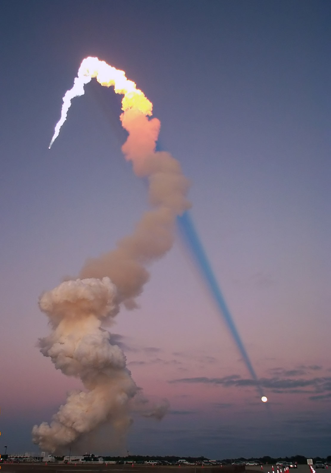
Currently, when the Sun is 1° above horizon, the light shaft (and shadow) is already gone. This looks not nice, e.g. when you look at the sphere in the direction of the Sun (the shadowed part): the sphere seems to start glowing for a while until the Sun goes below horizon.
With smoothstep edges of -0.026, -0.0035 instead of the current 0.02, 0.04 this looks much better but, when you look how the shadow extends into infinity, it goes into the sky:

I suppose this is normal, given this real-life photo (source):
Of course, the light shaft in the demo looks a bit wrong due to the lack of penumbra and corresponding too sharp shape. But was this the only reason to avoid extending light shaft into the sky by too early fading out?
I'm working on integrating this into my engine, which uses OpenSceneGraph rather than raw openGL functions. Because of this, I can't use the parts of model.h/cc that deal with opengl resources, but I would like to use the glsl header factory part. I'd like to suggest splitting model.h/cc into two classes, one class to generate the glsl header from the atmosphere params, and a different class (in different files) to setup the GL resources (textures etc). That way people can more easily use one without the other.
(Sorry, me again.)
I'm trying to build a version of this code which I can use in the material editor of Unreal Engine. For that, I need to actually output the textures so that I can use them there. So I'm going through the code trying to strip all the GL stuff away so that I can essentially just have pure code for generating the textures. This is proving more complicated than I hoped.
Before I even get to the issue of the 3D textures (since UE4 can use them internally, but not in the material editor), I am just trying to output the 2D transmittance texture to see if everything is working how I would like.
Essentially what I'm doing is using the code in the demo scene to create an instance of the Model, which then uses the functions in the Model (the lambdas for wavelength functions and creation of density profiles) along with the code in the glsl_header_factory_ function to create an AtmosphereParameters struct, which I am then passing to the functions for computing transmittance.
The only alteration that I've made to the transmittance functions is that I have had to change ComputeTransmittanceToTopAtmosphereBoundaryTexture since I am not using gl. I have modified it so that it loops through all the pixels (from {0,0} to {255, 63}), gets the relevant UV value, and then uses GetRMuFromTransmittanceTextureUv followed by ComputeTransmittanceToTopAtmosphereBoundary to get the transmittance value. I am then writing this value to a 1-dimensional array of vector3 (actually FLinearColor in UE4) values.
Inside UE4, I am using a render canvas object to write these pixels and save them out to an HDR.
The pixels are written left to right, top to bottom, from the top left corner.
Here is the result: https://i.imgur.com/ZuTmedI.jpg
And here is a download link:
TransmittanceTexture4.zip
This looks nothing like the examples I have seen elsewhere, for example:
https://www.gamedev.net/forums/topic/647768-pre-computed-atmospheric-scattering-transmittance-table/
And the example on page 54 of this masters' thesis: http://www.sperlhofer.com/images/stories/atmospheric/thesis-sperlhofer.pdf
As well as looking totally different, there are two pixels in the bottom-left corner which are totally black, which I'm sure is an error?
But I've been going over and over this for days now, and I can't figure out what I'm doing wrong. I realise that this might not be possible to diagnose without seeing the code (which I'm happy to share), but I wondered whether it's possible to say what might have happened here just from seeing this image?
In case it helps to figure out where the problem is, here is a dump of the values in the AtmosphereParameters struct which is being passed for the transmittance calculations:
	solar_irradiance	{X=1.47399998 Y=1.85039997 Z=1.91198003 }
	sun_angular_radius	0.00467499997
	bottom_radius		63600.0000
	top_radius		64200.0000
	rayleigh_density
		layers
			[0]
			width		0.00000000000000000
			exp_term	1.0000000000000000
			exp_scale	-0.012500000000000001
			linear_term	0.00000000000000000
			constant_term	0.00000000000000000

			[1]
			width		0.00000000000000000
			exp_term	1.0000000000000000
			exp_scale	-0.012500000000000001
			linear_term	0.00000000000000000
			constant_term	0.00000000000000000
	rayleigh_scattering	{X=0.000580233929 Y=0.00135577621 Z=0.00331000052 }
	mie_density
		layers
			[0]
			width		0.00000000000000000
			exp_term	1.0000000000000000
			exp_scale	-0.083333333333333343
			linear_term	0.00000000000000000
			constant_term	0.00000000000000000

			[1]
			width		0.00000000000000000
			exp_term	1.0000000000000000
			exp_scale	-0.083333333333333343
			linear_term	0.00000000000000000
			constant_term	0.00000000000000000

	mie_scattering	{X=0.000399599987 Y=0.000399599987 Z=0.000399599987 }
	mie_extinction	{X=0.000444000005 Y=0.000444000005 Z=0.000444000005 }
	mie_phase_function_g	0.800000012
	absorption_density
		layers
			[0]
			width		250.00000000000000
			exp_term	0.00000000000000000
			exp_scale	0.00000000000000000
			linear_term	0.0066666666666666671
			constant_term	-0.66666666666666663

			[1]
			width		0.00000000000000000
			exp_term	0.00000000000000000
			exp_scale	0.00000000000000000
			linear_term	-0.0066666666666666671
			constant_term	2.6666666666666665
	absorption_extinction	{X=6.49716603e-05 Y=0.000188089994 Z=8.50166816e-06 }
	ground_albedo	{X=0.100000001 Y=0.100000001 Z=0.100000001 }
	mu_s_min	1.78023577
Does any of that look wrong? If so, then I'm messing things up in the early stages, if not them I'm messing things up in the transmittance computation.
I really appreciate any help with this, I'm pulling my hair out over here!
I'm using Chrome 83.0.4103.116 on win 7 with AMD Radeon R9 200. Chrome console is filled (256 times) with [.WebGL-000000000C0547A0] GL_INVALID_OPERATION: Two textures of different types use the same sampler location.
Hi!
The new version has become much clearer and more correct. Great work! Have you thought about adding ozone accounting to your implementation? According to the developers of the Terragen (https://www.youtube.com/watch?v=z__WZOh1wXU), it has a significant effect on the appearance of the atmosphere. Gustav Bodare and Edvard Sandberg in their work (http://publications.lib.chalmers.se/records/fulltext/203057/203057.pdf) suggested that ozone should be taken into account not by a separate layer but by a distribution depending on the height (in "3.2.5 Transmittance"). As I understand their proposal is based on this http://skyrenderer.blogspot.se/2012/10/ozone-absorption.html article by Peter Kutz.
Hi,
thanks for this amazing atmospheric model. The demo is very cool.
When I try to build from source, the compiler complains about not finding some include files, e.g.
./atmosphere/reference/definitions.h:53:10: fatal error: math/angle.h: No such file or directory
Can you tell me where to find the files belonging in the math directory like angle.h, binary_function.h, scalar_function.h, etc?
Thanks!
I was trying to add a dimensionful quantity into functions.glsl (Earth-Moon distance to experiment with solar eclipse in subsolar point), and it appeared that there's a mismatch between the units in which the GPU model works (supplies the values into the shader) and the units of the CPU model.
The particular variables which appear to be out of sync are:
const Length m = 1.0; inside definitions.glsl (used by GPU model)constexpr Length kLengthUnit = 1.0 * km; inside reference/model_test.cc, which is supplied to Model::Model, which, in turn, does things like std::to_string(bottom_radius / length_unit_in_meters) when constructing AtmosphereParameters for the shader.The result is that the shader code used by the GPU model works in kilometers, but m is defined as 1.0, so that e.g. using 3*m in the shader will give you three kilometers instead of three meters.
A trivial fix would be to redefine m to 1e-3, but this seems to be a fragile solution, since any change to kLengthUnit will bring this out of sync again.
my os is win10 64bit, use vs2017.
i use the cmake to generate project, the generate_project.bat has some error.
when i run the demo, create the shader failed.
0x000001b15f5084e0 "0(16) : error C0000: syntax error, unexpected identifier, expecting "::" at token "AtmosphereParameters"\n"
model.cc line 1030 std::string header = glsl_header_factory_(lambdas);
it like the shader source text(header) is wrong.
how to solve this?
Thanks.
Currently sun angular size has effect on how fast direct radiance fades when sun hides beneath the horizon.
http://i64.tinypic.com/14jyoh0.png
Correct me if I am wrong but should it also have effect on how fast sky radiance or indirect radiance fades into night or day during sunset or sunrise?
My apologies if this is a really stupid question.
I am trying to read this code in detail so that I can really understand it, but the formatting of the documentation is very strange.
It kinda looks like HTML (with all the paragraph tags etc. and SVG sections) but when I copy-pasted the code into an HTML file and opened it up, it's all over the place.
And where on an SVG diagram a point is labelled, for example, 'b', it's listed in the documenation like this:
And then there are sections like this:
Which I presume should look a lot simpler!
How can I view this code in the way intended so that it is intelligible?
Thanks!
Please help.
Apparently. None of the developers I have hired to get this project set up can do it in visual studio. Everyone is complaining that the code has "too many errors" and does not compile.
So if others got it working. Not sure why my developer can't. I asked him what errors he has. He can't even tell me.
Does anyone have a pre compiled version of this full project at all? To make using this not so frustrating.
Can someone update this? Or help me get this running in Visual Studio 2019.
Hi,
I was playing around with this code in a VR rendering and I noticed that I get artifacts if I set the scale (kLengthUnitInMeters) to be 1m (to give realistic scales for earth). From experience, these artifacts seem to be from catastrophic cancellation in your shader routines when you calculate the intersection distance using the quadratic formula.
I'm currently pulling together a patch set to fix this, but I'm posting this issue first to check if you have any comment about this: i.e, are you already aware of this and is there something more that needs work that I've overlooked?
This is not an issue, just a post of appreciation! I recently integrated your model into CosmoScout VR and was surprised both by how smoothly this went and by the visual results.
And the results are pretty amazing! We also see the precision-related issues at the horizon with high exposure values but most of the time it produces stunning results! Thank you very much for making this implementation available!


Hi!
Thank you for the awesome demo.
Is it possible to change the spectrum (temperature) of the star?
The emittance at a given wavelength can be calculated from temperature by Planck's radiation law, but where should I give the calculated values to the Model, to use it as the star's color?
Currently, the sky after sunset becomes completely dark. However, atmosphere is never completely dark
and during night, when rayleigh scattering stops dominating, some phenomena appear like airglow or moonlight scattering which gives tint of blue or green, of course very subtle when compared to rayleigh scattering during day.
Is it possible to conduct some research and add such experimental feature which would enrich the project and wouldn't hurt real time performance?
Here is effect of ozone in current implementation. On the left - enabled with default Dobson unit as in demo, 4 scattering orders and same Rayleigh scattering factor. On the left disabled. Gamma is enhanced a little.

Here is comparison in Terragen 4.

The right sides are similar. But I wonder about the ozone sides which differ - it gets more violet in current implementation than deep bluish as seen in Terragen or some real sky observation.
I tried to regulate it by changing the Dobson unit but it seems to abruptly change from right to left colors.
Can this be enhanced somewhat without increasing number of scattering orders much? Thank you.
Hello! I am using your reference implementation during many years in SpaceEngine. Recently implemented a HDR rendering with autoexposure, and encountered with a major problem. Assuming at daytime we have exposure of 10, at dawn it increases to ~1000, and at a night it increases to ~10^5. At such large exposure, one can observe following problems:
A blocky artifacts near the horizon, which fades abruptly as sun goes deeper under horizon (see this pictrure). Size of those blocks can be reduced by increasing SCATTERING_TEXTURE_NU_SIZE four times. Step between "fades" can be reduced by increasing SCATTERING_TEXTURE_MU_S_SIZE four times, but even this is not enough. This is a bad solution, because memory requirements and precomputation times grows absurdly. Maybe changing the mapping parametrization could help? I also thinking of changing linear texture filtering to cubic, but it is more costly.
Orange glow on horizon (the "last sunset step") does not fade away even when sun zenith angle is 120. From space it is look like a silverglow of the atmosphere where it must not be visible (picture). This problem can be solved by increasing kMaxSunZenithAngle to 180, but does this makes resolution of the scattering texture in MuS worse?
Color distortions are visible soon after sunset. See this picture. Sometimes thing on the left became green.
Sharp edge is seen from space.
Not related to abovemantioned, but this implementation has seams at horizon.
Thanks for advise!
Hi!
Can your sky model we used for estimating the infrared irradiance into a surface, in W*m-2? I'm asking this because I see that your papers seem to be limited to the visible spectrum, but at the same time you have researched a lot about the sky physics, so maybe you can provide some advice about this.
What I want to simulate is heating of surfaces due to the Sun and the sky dome. At the moment I was looking at the (luminance-only) Perez model, but then I learnt about your model and wondered if it could be more realistic than Perez for the infrared radiation.
What is the math library used? My build fails like:
./atmosphere/reference/definitions.h:53:10: fatal error: math/angle.h: No such file or directory
#include "math/angle.h"
Hey!
I'm working on integrating your demo into my engine at the moment and I have a couple of issues:
How would I replace the calculations performed in Demo::HandleReshapeEvent(int viewport_width, int viewport_height) with a call to glm::projection()? I tried to do a simple replacement however the scene ends up being squished in the vertical (+y) direction:
const auto mat = glm::perspective(glm::radians(45.0f), 1280.0f / 720.0f, 1.0f, 1000.0f); glUniformMatrix4fv(glGetUniformLocation(program_, "view_from_clip"), 1, false, value_ptr(mat));

Also, in the void Demo::HandleRedisplayEvent() const function, where you calculate the "model_from_view", and "camera" uniforms, is the former simply a call to glm::lookat(), and the latter just the camera position (I have a Camera class that handles movement, orientation, etc., so I just want to keep things centralized instead of having to convert back and forth every frame)?
Thanks so much in advance!
A declarative, efficient, and flexible JavaScript library for building user interfaces.
🖖 Vue.js is a progressive, incrementally-adoptable JavaScript framework for building UI on the web.
TypeScript is a superset of JavaScript that compiles to clean JavaScript output.
An Open Source Machine Learning Framework for Everyone
The Web framework for perfectionists with deadlines.
A PHP framework for web artisans
Bring data to life with SVG, Canvas and HTML. 📊📈🎉
JavaScript (JS) is a lightweight interpreted programming language with first-class functions.
Some thing interesting about web. New door for the world.
A server is a program made to process requests and deliver data to clients.
Machine learning is a way of modeling and interpreting data that allows a piece of software to respond intelligently.
Some thing interesting about visualization, use data art
Some thing interesting about game, make everyone happy.
We are working to build community through open source technology. NB: members must have two-factor auth.
Open source projects and samples from Microsoft.
Google ❤️ Open Source for everyone.
Alibaba Open Source for everyone
Data-Driven Documents codes.
China tencent open source team.
