Code Monkey home page Code Monkey logo

hlw8012's Introduction

Hello 👋

Thanks for visiting my GitHub profile. Some info about me:

  • 🧑‍🏭 I work as Product Owner at RAKwireless
  • 💻 I'm a freelancer working on IoT projects, know more about me on my blog: Tinkerman
  • 🎓 But actually, I studied asthrophysics. Loved it, but hard to make a living out of it.
  • 🌍 Based in: Sant Pol de Mar, Catalunya
  • 👻 Profiles: Linkedin, Twitter, Telegram

Xose's github stats

Readme Card Readme Card Readme Card Readme Card Readme Card Readme Card

hlw8012's People

Contributors

herm avatar ivankravets avatar xoseperez avatar

Stargazers

 avatar  avatar  avatar  avatar  avatar  avatar  avatar  avatar  avatar  avatar  avatar  avatar  avatar  avatar  avatar  avatar  avatar  avatar  avatar  avatar  avatar  avatar  avatar  avatar  avatar  avatar  avatar  avatar  avatar  avatar  avatar  avatar  avatar  avatar  avatar  avatar  avatar  avatar  avatar  avatar  avatar  avatar  avatar  avatar  avatar  avatar  avatar  avatar  avatar  avatar  avatar  avatar  avatar  avatar  avatar  avatar  avatar  avatar  avatar  avatar  avatar  avatar  avatar  avatar  avatar  avatar  avatar  avatar  avatar  avatar  avatar  avatar  avatar  avatar  avatar  avatar  avatar  avatar  avatar  avatar  avatar  avatar  avatar  avatar  avatar  avatar  avatar  avatar  avatar  avatar  avatar  avatar  avatar  avatar  avatar  avatar  avatar  avatar  avatar  avatar

Watchers

 avatar  avatar  avatar  avatar  avatar  avatar  avatar  avatar  avatar  avatar  avatar  avatar  avatar  avatar  avatar

hlw8012's Issues

Document a safe way to develop code and algorithms for the HLW8012

Originally reported by: Julian Todd (Bitbucket: goatchurch, GitHub: Unknown)


For most arduino sensors, I program the algorithms and send print statements through the serial line in order to debug it.

But everywhere it says DO NOT CONNECT TO SERIAL LINE WHEN THE HLW8012 IS WORKING (ie when it is connected to the mains).

It's good to be told what not to do. But even nicer to be told how we should do it instead.

current == active power ?

I hacked a small wifi stwitch with hlw8012 to test with espurna. In espurna the shown current seems not to be the active current, it seems to be the reactive or apparent current. Is that intended ? I mean if I plug a comsumer with 21 W active power, espurna shows 21 W active power and 9.285 A current ...I mean this is not what we want to know or am I wrong ?

Voltage and current power formula

Hello, I don't understand where "1000000.0" in the calculation formula comes from, the value I calculated with the formula and the deviation I measured with the power meter。

_current_multiplier = (1000000.0 * 512 * V_REF / _current_resistor / 24.0 / F_OSC);
_voltage_multiplier = (2000000.0 * 512 * V_REF * _voltage_resistor / 2.0 / F_OSC);
_power_multiplier = (1000000.0 * 128 * V_REF * V_REF * _voltage_resistor / _current_resistor / 48.0 / F_OSC);

ESP crash when using interrupts + webserver

Originally reported by: Alexander Christian (Bitbucket: alexander_christian, GitHub: Unknown)


I'm using just the HLW8012 lib with my own sketch, which includes a webserver presenting the measurements...
When using interrupts I face the following stacktrace when opening/loading the webpage:

#!arduino

0x40107314: interrupt_handler at ?? line ?
0x4010078f: ppProcessTxQ at ?? line ?
0x4020521e: HLW8012::cf1_interrupt() at ?? line ?
0x4010078f: ppProcessTxQ at ?? line ?
0x401072dc: interrupt_handler at ?? line ?
0x4020856c: hlw8012_cf1_interrupt() at ?? line ?
0x40107378: interrupt_handler at ?? line ?
0x40107362: interrupt_handler at ?? line ?
0x401048f9: ets_timer_disarm at ?? line ?
0x401072dc: interrupt_handler at ?? line ?
0x402101f0: pm_get_sleep_type at ?? line ?
0x40104e5e: spi_flash_read at ?? line ?
0x401077b4: pvPortZalloc at ?? line ?
0x4020fcb5: pm_set_sleep_time at ?? line ?
0x40210156: pm_get_sleep_type at ?? line ?
0x4021c7c8: tcpip_tcp_timer at /Users/igrokhotkov/espressif/arduino/tools/sdk/lwip/src/core/timers.c line 81
0x40210203: pm_get_sleep_type at ?? line ?
0x40212edd: ets_timer_handler_isr at ?? line ?
0x40212f22: ets_timer_handler_isr at ?? line ?

This also happens when no load is connected. So I guess it's not really load-related (like this very similar issue with very similar stack trace: https://bitbucket.org/xoseperez/espurna/issues/3/sonoff-pow-crash-with-high-wattage), but rather a kind of interrupt issue. Maybe in combination with the webserver?!

If I don't open/load/refresh the webpage, there's no crash.

If I switch to non-interrupt-mode, there is also no crash. But having precise measurement without interrupt (timeout >500ms, f.i. 5sec) will block the webserver :-( Even 500ms will give a bad user experience when loading the page.

Pls. help...

NO LOAD READINGS ARE FUNNY

hello @xoseperez i am trying your code in my project for measuring current, voltage power and power factor but somehow it is not working properly or i am unable to ride it properly i am using the code from basic.ino hlw8012 please help.At no load it is giving me readings like Voltage = 0, 480,36000, 0,75... similar to current and power

#include <Arduino.h>
#include "HLW8012.h"

#define SERIAL_BAUDRATE 115200

// GPIOs
#define RELAY_PIN 12
#define SEL_PIN 5
#define CF1_PIN 13
#define CF_PIN 14

// Check values every 2 seconds
#define UPDATE_TIME 2000

// Set SEL_PIN to HIGH to sample current
// This is the case for Itead's Sonoff POW, where a
// the SEL_PIN drives a transistor that pulls down
// the SEL pin in the HLW8012 when closed
#define CURRENT_MODE HIGH

// These are the nominal values for the resistors in the circuit
#define CURRENT_RESISTOR 0.001
#define VOLTAGE_RESISTOR_UPSTREAM ( 5 * 470000 ) // Real: 2280k
#define VOLTAGE_RESISTOR_DOWNSTREAM ( 1000 ) // Real 1.009k

HLW8012 hlw8012;

void unblockingDelay(unsigned long mseconds) {
unsigned long timeout = millis();
while ((millis() - timeout) < mseconds) delay(1);
}

void calibrate() {

// Let's first read power, current and voltage
// with an interval in between to allow the signal to stabilise:

hlw8012.getActivePower();

hlw8012.setMode(MODE_CURRENT);
unblockingDelay(2000);
hlw8012.getCurrent();

hlw8012.setMode(MODE_VOLTAGE);
unblockingDelay(2000);
hlw8012.getVoltage();

// Calibrate using a 60W bulb (pure resistive) on a 230V line
hlw8012.expectedActivePower(60.0);
hlw8012.expectedVoltage(230.0);
hlw8012.expectedCurrent(60.0 / 230.0);

// Show corrected factors
Serial.print("[HLW] New current multiplier : "); Serial.println(hlw8012.getCurrentMultiplier());
Serial.print("[HLW] New voltage multiplier : "); Serial.println(hlw8012.getVoltageMultiplier());
Serial.print("[HLW] New power multiplier   : "); Serial.println(hlw8012.getPowerMultiplier());
Serial.println();

}

void setup() {

// Init serial port and clean garbage
Serial.begin(SERIAL_BAUDRATE);
Serial.println();
Serial.println();

// Close the relay to switch on the load
pinMode(RELAY_PIN, OUTPUT);
digitalWrite(RELAY_PIN, HIGH);

// Initialize HLW8012
// void begin(unsigned char cf_pin, unsigned char cf1_pin, unsigned char sel_pin, unsigned char currentWhen = HIGH, bool use_interrupts = false, unsigned long pulse_timeout = PULSE_TIMEOUT);
// * cf_pin, cf1_pin and sel_pin are GPIOs to the HLW8012 IC
// * currentWhen is the value in sel_pin to select current sampling
// * set use_interrupts to false, we will have to call handle() in the main loop to do the sampling
// * set pulse_timeout to 500ms for a fast response but losing precision (that's ~24W precision :( )
hlw8012.begin(CF_PIN, CF1_PIN, SEL_PIN, CURRENT_MODE, false, 500000);

// These values are used to calculate current, voltage and power factors as per datasheet formula
// These are the nominal values for the Sonoff POW resistors:
// * The CURRENT_RESISTOR is the 1milliOhm copper-manganese resistor in series with the main line
// * The VOLTAGE_RESISTOR_UPSTREAM are the 5 470kOhm resistors in the voltage divider that feeds the V2P pin in the HLW8012
// * The VOLTAGE_RESISTOR_DOWNSTREAM is the 1kOhm resistor in the voltage divider that feeds the V2P pin in the HLW8012
hlw8012.setResistors(CURRENT_RESISTOR, VOLTAGE_RESISTOR_UPSTREAM, VOLTAGE_RESISTOR_DOWNSTREAM);

// Show default (as per datasheet) multipliers
Serial.print("[HLW] Default current multiplier : "); Serial.println(hlw8012.getCurrentMultiplier());
Serial.print("[HLW] Default voltage multiplier : "); Serial.println(hlw8012.getVoltageMultiplier());
Serial.print("[HLW] Default power multiplier   : "); Serial.println(hlw8012.getPowerMultiplier());
Serial.println();

//calibrate();

}

void loop() {

static unsigned long last = millis();

// This UPDATE_TIME should be at least twice the minimum time for the current or voltage
// signals to stabilize. Experimentally that's about 1 second.
if ((millis() - last) > UPDATE_TIME) {

    last = millis();
    Serial.print("[HLW] Active Power (W)    : "); Serial.println(hlw8012.getActivePower());
    Serial.print("[HLW] Voltage (V)         : "); Serial.println(hlw8012.getVoltage());
    Serial.print("[HLW] Current (A)         : "); Serial.println(hlw8012.getCurrent());
    Serial.print("[HLW] Apparent Power (VA) : "); Serial.println(hlw8012.getApparentPower());
    Serial.print("[HLW] Power Factor (%)    : "); Serial.println((int) (100 * hlw8012.getPowerFactor()));
    Serial.println();

    // When not using interrupts we have to manually switch to current or voltage monitor
    // This means that every time we get into the conditional we only update one of them
    // while the other will return the cached value.
    hlw8012.toggleMode();

}

}

it's not only that i have taken no load readings i also connected 20W bulb to it and then got weird readings. PLEASE HELP

Some readings contain only 0 values (sonoff POW v2)

I created a minimal sketch to reproduce this using a sonoff POW v2 device. I attached a 25W purely resistive light bulb.
HLW8012_Basic_POW.txt

The readings are as follows:
(D) Active Power (W) : 26
(D) Current (A) : 0.10
(D) Apparent Power (VA) : 0
(D) Power Factor (%) : 100
(D)
(D) Active Power (W) : 0
(D) Current (A) : 0.00
(D) Apparent Power (VA) : 0
(D) Power Factor (%) : 100
(D)
(D) Active Power (W) : 26
(D) Current (A) : 0.10
(D) Apparent Power (VA) : 0
(D) Power Factor (%) : 0
(D)
(D) Active Power (W) : 0
(D) Current (A) : 0.00
(D) Apparent Power (VA) : 0
(D) Power Factor (%) : 0

Between the readings there is a break of 10 seconds. The sensor should not be overloaded.
Sometimes there are several readings with zeroes, until I get a correct reading again.
Does somebody have an idea, what I'm missing here?

Multiple HLW8012

Hey Xose, I am working on a Home Automation product which will be able to send Energy Measurement using this HLW8012 module (Link: https://www.electrodragon.com/product/energy-meter-hlw8012-breakout-board/). Thanks to you we were able to work with 1 Module. The problem comes when we try to connect multiple modules with same MCU giving them power from an isolated source(Hi-link HLK-PM01) the problems is when we switch on one HLW8012 the other HLW8012 module which is connected to power source (Hi-link HLK-PM01) but the switch is off still gets the AC power which in-turn switch on the device.

Please Help us with guiding for developing a module which is able to Get power reading from 4 different Appliances using the same isolated power source.

Thanks,
Abhi Ratnman
[email protected]

Cloning issue in Platformio

I'm trying to build espurna project in platformio, but I get a fatal error when trying to clone hlw8012.

´´Cloning into 'C:\Temp\espurna-1.12.5\code.piolibdeps_tmp_installing-kzaloo-package'...
warning: Could not find remote branch 1.1.0 to clone.
fatal: Remote branch 1.1.0 not found in upstream origin´´

I'm not sure if this is an hlw8012 issue, but I would appreciate your comment on it.

Thanks!

Sonoff POW v2

Hello Xose
Thanks for your library. I used the one from Andreas Spiess https://github.com/SensorsIot/Sonoff-POW before. It does not work anymore, probably because of updates in other Arduino libraries. I'm not good enough to debug this.

So I use your library for my own code, running on the Sonoff POW v2 devices.
I measure power and current, the voltage is 230V (very stable in Switzerland).
From the code with the 25W bulb I get a power-reading of 25.0 , perfect. For this I ran the calibrate() routine once in my code. Here is the output:
(D) [HLW] New current multiplier : 14484.49
(D) [HLW] New voltage multiplier : 408636.51
(D) [HLW] New power multiplier : 11754104.24
Question 1: can I use the readings and set them in all my sonoff POW devices without calibration?
For example with something like:
hlw8012.setCurrentMultiplier(14484.49);

Question 2: the current reading is always 0.0
I use exactly your code, just added a wireless connection and the telnet debug library to get the debug output via telnet without electrocuting my poor MacBook.
Do you have any hints?

Submitting PRs here seems to be disabled

Originally reported by: pjz (Bitbucket: pjz, GitHub: pjz)


I forked the repo and made a branch with a fix for Issue #5 that I also just created, but trying to create a Pull Request for you gets me the web equivalent of E_PERM.

Feel free to merge it if you like it, or fix it, or whatever - I just need the functionality and thought you might like a contribution.

CSE7759

There are now another version of Son off Pow with the chip CSE7759. They are very similar. May be we can use your library changing the constants?
Can you take a look on the schematics?
Thanks!

Zero values when using this library for ESP32

Hello, Im using this HLW8012 library with my ESP32 but somehow not able to get the values for Current/Voltage/Power :( I tried both Interrupt based as well as Continuous value read methods yet no success. Did anyone use that library with ESP32? Do I need to modify anything to make it work for ESP32? Have not got any compile /run time issues. Always getting value as 0, Verified with debugs and im going inside all the functions.

Nothing happens after uploading the code for sonoff pow

After successfully uploading the code with much difficulty, the hotspot mode does not turn on and even in serial monitor, nothing is displayed.
To compile the code, I have changed the .ipp files into .hpp. And of course uncommented the necessary lines in /config/general.h

I added these libraries in the code in main.h:

#include "AsyncEventSource.h"
#include "AsyncJson.h"
#include "AsyncWebSocket.h"
#include "AsyncWebSynchronization.h"
#include "ESPAsyncWebServer.h"
#include "SPIFFSEditor.h"
#include "StringArray.h"
#include "WebAuthentication.h"
#include "WebHandlerImpl.h"
#include "WebResponseImpl.h"
#include "hlw8012.h"
#include "DebounceEvent.h"
#include "ESPAsyncUDP.h"

Thanks in advance.

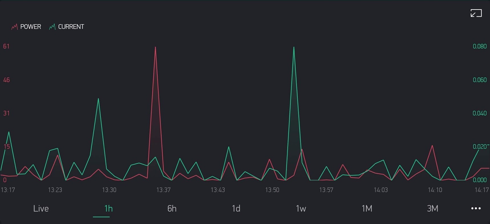
Random readings when no load\relay off

I've just uploaded the interrupts example to a Sonoff POW, once or twice a minute I get random readings - is that to be expected? (I want to use the POW to determine if a device is switched on and for how long so was triggering on if current > x).

Most of the time with no load:

t1

Randomly with relay off:
t2

1 Hour history:
screenshot_20181025-141739_blynk

#define BLYNK_PRINT Serial
#include <Arduino.h>
#include "HLW8012.h"
#include <ESP8266WiFi.h>
#include <BlynkSimpleEsp8266.h>

#define SERIAL_BAUDRATE                 115200

// GPIOs
#define RELAY_PIN                       12
#define SEL_PIN                         5
#define CF1_PIN                         13
#define CF_PIN                          14
#define UPDATE_TIME                     5000
#define CURRENT_MODE                    HIGH

// These are the nominal values for the resistors in the circuit
#define CURRENT_RESISTOR                0.001
#define VOLTAGE_RESISTOR_UPSTREAM       ( 5 * 470000 ) // Real: 2280k
#define VOLTAGE_RESISTOR_DOWNSTREAM     ( 1000 ) // Real 1.009k

char auth[] = "";
char ssid[] = "";
char pass[] = "";

HLW8012 hlw8012;

void ICACHE_RAM_ATTR hlw8012_cf1_interrupt() {
  hlw8012.cf1_interrupt();
}
void ICACHE_RAM_ATTR hlw8012_cf_interrupt() {
  hlw8012.cf_interrupt();
}

void setInterrupts() {
  attachInterrupt(CF1_PIN, hlw8012_cf1_interrupt, CHANGE);
  attachInterrupt(CF_PIN, hlw8012_cf_interrupt, CHANGE);
}

void setup() {

  // Init serial port and clean garbage
  Serial.begin(SERIAL_BAUDRATE);
  Blynk.begin(auth, ssid, pass);
  // Close the relay to switch on the load
  pinMode(RELAY_PIN, OUTPUT);
  digitalWrite(RELAY_PIN, HIGH);


  hlw8012.begin(CF_PIN, CF1_PIN, SEL_PIN, CURRENT_MODE, true);
  hlw8012.setResistors(CURRENT_RESISTOR, VOLTAGE_RESISTOR_UPSTREAM, VOLTAGE_RESISTOR_DOWNSTREAM);

  setInterrupts();

}

char buffer[50];

void loop() {
  Blynk.run();
  static unsigned long last = millis();

  // This UPDATE_TIME should be at least twice the interrupt timeout (2 second by default)
  if ((millis() - last) > UPDATE_TIME) {

    last = millis();

    Blynk.virtualWrite(V1, hlw8012.getActivePower());
    Blynk.virtualWrite(V2, hlw8012.getVoltage());
    Blynk.virtualWrite(V3, hlw8012.getCurrent());
    Blynk.virtualWrite(V4, hlw8012.getApparentPower());
    Blynk.virtualWrite(V5, (int) (100 * hlw8012.getPowerFactor()));
    Blynk.virtualWrite(V6, hlw8012.getEnergy());

  }
}

HLW8012 board calibration

seams this one is also becoming popular.

but i'm not find out to calibarte it. any help?

Thx in advance.

HLW8012_High-Precision_Energy_Metering_Module_Arduino_Energy_Monitoring

Pull request: Energy monitoring

Originally reported by: Hermann Kraus (Bitbucket: hermr2d2, GitHub: Unknown)


This is actually a pull request, but I can't open one directly ("Access denied").
Please pull from https://bitbucket.org/hermr2d2/hlw8012.

It adds a function to directly measure the energy. This helps in at least two scenarios:

  1. Measure how much energy a device uses per day.
  2. Measure very low power devices. As this does no numerical integration is quite accurate if you measure over a long time.

Measurement not that precise?!

Originally reported by: Alexander Christian (Bitbucket: alexander_christian, GitHub: Unknown)


I'm facing some issues with measurement with my Sonoff POW (which uses this HLW8012 chip). Sometimes the measurement is totally wrong and not realistic. So I decided to test with no load to see if there are also strange values visible. And guess what:

Sometimes there is some current, where not current should be (measurement with 5sec interval):

Bildschirmfoto vom 2017-11-24 14-53-19.png

My guess is, this also happen when there is a load connected, but then the failure is even worse.

Measuring is done via interrupts.

Is anyone else facing those issues?

Connect to non PWM pin

Hello just curious, can I connect the output from HLW8012 to non PWM pin on my arduino ?

HLW8012 CP1 frequency capping

I'm currently designing a circuit that contains the HLW8012.
But I'm having a problem with the CF1 pin capping at 1.7kHz output, while in current mode.
The circuit I use is the one provided in the datasheet of the HLW8012, with the MCU connected directly to the HLW8012 pin.
I have tried replacing components in case it was a bad component, but no luck so far.
Since non of this worked I tried to start with a low current and increasing it to see where it caps.

My results were as follows:
0.323A -> 348Hz
0.523A -> 561Hz
0.716A -> 753Hz
1.256A -> 1332Hz
1.563A -> 1602Hz
1.673A -> 1724Hz
Everything above the 1.6A gets a frequency of around 1700Hz (1.7kHz).
(For the load, I used multiple lamps that consume between 50-120W)

Any idea's what could cause this problem?

Multipliers for Gosund SP1?

I am trying to make a sense out of the readings the HLW8012 library gives me for the Gosund SP1 plug.

The raw values I get with the default settings:

#define SEL_PIN 12
#define CF_PIN 4
#define CF1_PIN 5 
#define UPDATE_TIME 2000
#define CURRENT_RESISTOR                0.001
#define VOLTAGE_RESISTOR_UPSTREAM       ( 5 * 470000 ) // Real: 2280k
#define VOLTAGE_RESISTOR_DOWNSTREAM     ( 1000 ) // Real 1.009k
...
setup() {
...
hlw8012.begin(CF_PIN, CF1_PIN, SEL_PIN, LOW, false, 500000);
hlw8012.setResistors(CURRENT_RESISTOR, VOLTAGE_RESISTOR_UPSTREAM, VOLTAGE_RESISTOR_DOWNSTREAM);
...
loop() {
...
    if ((millis() - last) > UPDATE_TIME) {
      char buf[80];

      snprintf(buf, 80, "Power = %d W\n", hlw8012.getActivePower()); TelnetMsg(buf);
      snprintf(buf, 80, "Voltage = %d V\n", hlw8012.getVoltage()); TelnetMsg(buf);
      snprintf(buf, 80, "Current = %f A\n", hlw8012.getCurrent()); TelnetMsg(buf);
      snprintf(buf, 80, "Apparent = %d W\n", hlw8012.getApparentPower()); TelnetMsg(buf);
      snprintf(buf, 80, "Factor = %d %%\n\n", (int) (100 * hlw8012.getPowerFactor())); TelnetMsg(buf);

      // When not using interrupts we have to manually switch to current or voltage monitor
      // This means that every time we get into the conditional we only update one of them
      // while the other will return the cached value.
      hlw8012.toggleMode();

      last = millis();
    }
...

are quite off. These are the values from the lib (with a soldering station attached to the plug):

Power = 129295 W
Voltage = 5675 V
Current = 181.056161 A
Apparent = 1027493 W
Factor = 12 %

Power = 129295 W
Voltage = 5376 V
Current = 181.056161 A
Apparent = 924653 W
Factor = 12 %

Power = 126141 W
Voltage = 5675 V
Current = 181.056161 A
Apparent = 1027493 W
Factor = 11 %

A cheap power meter set in between shows these readings (varying a bit, as the soldering station is levelling the tip temperature):

Power = 5 to ~35 Watts
Voltage = 228 to 231 Volts

What are the multipliers required to correct the values?

Multiple instances of HLW8012 class with interrupts?

So I've been digging into this for a while now, and I'm trying to come up with a good solution but am currently stumped, and figured I'd go right to the source.

I have a project where I want to attach more than one HLW8012 board/chip to a single Arduino, then every interval return the values for all of them. In short, a PDU, more than a single smart plug. And for the sake of argument I have an Arduino with at least 4 PWM inputs (so not an Uno). So I create an array of instances of the HLW8012 class inside a simple struct like so:

struct Sensor {
    String   label;              // Sensor label/name
    HLW8012* hlw;                // Class instance of HLW8012 library
    int      sel_pin;            // Digital output pin for sel
    int      cf1_pin;            // Digital PWM-capable input pin for cf1
    int      cf_pin;             // Digital PWM-capable input pin for cf
};
const Sensor SensorDatabase[] = {
    (Sensor) { "01A", new HLW8012, 1,  2,  3 },
    (Sensor) { "01B", new HLW8012, 4,  5,  6 }
};
const int SensorCount = 2;

I then initialize them in a loop:

void setup() {
    // Initialize the HLW8012 module for each sensor entry
    for (int s = 0; s < SensorCount; s++) {
        // Initialize HLW8012 class instance
        SensorDatabase[s].hlw->begin(SensorDatabase[s].cf_pin, SensorDatabase[s].cf1_pin, SensorDatabase[s].sel_pin, HIGH, true);

        // Set the nominal value of the resistors
        SensorDatabase[s].hlw->setResistors(CURRENT_RESISTOR, VOLTAGE_RESISTOR_US, VOLTAGE_RESISTOR_DS);
      
		// ???????????
    }
}

The issue comes with the attachInterrupt calls, which I presume I would want to do in the ????? bit above. One fairly obvious but non-working attempt:

attachInterrupt(digitalPinToInterrupt(SensorDatabase[s].cf_pin), SensorDatabase[s].hlw->cf_interrupt, CHANGE);
attachInterrupt(digitalPinToInterrupt(SensorDatabase[s].cf1_pin), SensorDatabase[s].hlw->cf1_interrupt, CHANGE);
error: invalid use of non-static member function
attachInterrupt(digitalPinToInterrupt(SensorDatabase[s].cf_pin), SensorDatabase[s].hlw->cf_interrupt, CHANGE);

error: invalid use of non-static member function
attachInterrupt(digitalPinToInterrupt(SensorDatabase[s].cf1_pin), SensorDatabase[s].hlw->cf1_interrupt, CHANGE);

Since these have to take a pointer to a function with no arguments that returns a void, I can't find a way to do this - all of the methods seem to require these to be static functions, but doing so seems non-trivial. I've tried looking for other more general solution, but a solid number of them recommend workarounds that don't seem to go anywhere (stuff like std::bind, using various constructors there, and of course the wrapper function idea that is used in the interrupts example but is hard to scale like this).

Does anyone have any advice about this specific library, and what if anything I might need to do to it to make this work how I'd like - initialize multiple instance of the class each bound to interrupts on different pins in a semi-dynamic (array) way?

Wrong value for VOLTAGE_RESISTOR_UPSTREAM in examples?

Hi there,

I'm wonder if the definition of VOLTAGE_RESISTOR_UPSTREAM in the examples (HLW8012_Basic & HLW8012_Interrupts) is right , as it corresponds to a chain of 5 resistors, 470 Kohms each.

#define VOLTAGE_RESISTOR_UPSTREAM (5 * 470000)

However, the datasheet shows a chain of 6 resistors, 470 Kohms each for the V2P pin, so as per my knowledge, the constant definition should be like this:

#define VOLTAGE_RESISTOR_UPSTREAM (6 * 470000)

Am I right?

Recommend Projects

  • React photo React

    A declarative, efficient, and flexible JavaScript library for building user interfaces.

  • Vue.js photo Vue.js

    🖖 Vue.js is a progressive, incrementally-adoptable JavaScript framework for building UI on the web.

  • Typescript photo Typescript

    TypeScript is a superset of JavaScript that compiles to clean JavaScript output.

  • TensorFlow photo TensorFlow

    An Open Source Machine Learning Framework for Everyone

  • Django photo Django

    The Web framework for perfectionists with deadlines.

  • D3 photo D3

    Bring data to life with SVG, Canvas and HTML. 📊📈🎉

Recommend Topics

  • javascript

    JavaScript (JS) is a lightweight interpreted programming language with first-class functions.

  • web

    Some thing interesting about web. New door for the world.

  • server

    A server is a program made to process requests and deliver data to clients.

  • Machine learning

    Machine learning is a way of modeling and interpreting data that allows a piece of software to respond intelligently.

  • Game

    Some thing interesting about game, make everyone happy.

Recommend Org

  • Facebook photo Facebook

    We are working to build community through open source technology. NB: members must have two-factor auth.

  • Microsoft photo Microsoft

    Open source projects and samples from Microsoft.

  • Google photo Google

    Google ❤️ Open Source for everyone.

  • D3 photo D3

    Data-Driven Documents codes.