Code Monkey home page Code Monkey logo

python-periphery's Introduction

python-periphery Tests Status Docs Status GitHub release License

Linux Peripheral I/O (GPIO, LED, PWM, SPI, I2C, MMIO, Serial) with Python 2 & 3

python-periphery is a pure Python library for GPIO, LED, PWM, SPI, I2C, MMIO, and Serial peripheral I/O interface access in userspace Linux. It is useful in embedded Linux environments (including Raspberry Pi, BeagleBone, etc. platforms) for interfacing with external peripherals. python-periphery is compatible with Python 2 and Python 3, is written in pure Python, and is MIT licensed.

Using Lua or C? Check out the lua-periphery and c-periphery projects.

Contributed libraries: java-periphery, dart_periphery

Installation

With pip:

pip install python-periphery

With easy_install:

easy_install python-periphery

With setup.py:

git clone https://github.com/vsergeev/python-periphery.git
cd python-periphery
python setup.py install

Examples

GPIO

from periphery import GPIO

# Open GPIO /dev/gpiochip0 line 10 with input direction
gpio_in = GPIO("/dev/gpiochip0", 10, "in")
# Open GPIO /dev/gpiochip0 line 12 with output direction
gpio_out = GPIO("/dev/gpiochip0", 12, "out")

value = gpio_in.read()
gpio_out.write(not value)

gpio_in.close()
gpio_out.close()

Go to GPIO documentation.

LED

from periphery import LED

# Open LED "led0" with initial state off
led0 = LED("led0", False)
# Open LED "led1" with initial state on
led1 = LED("led1", True)

value = led0.read()
led1.write(value)

# Set custom brightness level
led1.write(led1.max_brightness / 2)

led0.close()
led1.close()

Go to LED documentation.

PWM

from periphery import PWM

# Open PWM chip 0, channel 10
pwm = PWM(0, 10)

# Set frequency to 1 kHz
pwm.frequency = 1e3
# Set duty cycle to 75%
pwm.duty_cycle = 0.75

pwm.enable()

# Change duty cycle to 50%
pwm.duty_cycle = 0.50

pwm.close()

Go to PWM documentation.

SPI

from periphery import SPI

# Open spidev1.0 with mode 0 and max speed 1MHz
spi = SPI("/dev/spidev1.0", 0, 1000000)

data_out = [0xaa, 0xbb, 0xcc, 0xdd]
data_in = spi.transfer(data_out)

print("shifted out [0x{:02x}, 0x{:02x}, 0x{:02x}, 0x{:02x}]".format(*data_out))
print("shifted in  [0x{:02x}, 0x{:02x}, 0x{:02x}, 0x{:02x}]".format(*data_in))

spi.close()

Go to SPI documentation.

I2C

from periphery import I2C

# Open i2c-0 controller
i2c = I2C("/dev/i2c-0")

# Read byte at address 0x100 of EEPROM at 0x50
msgs = [I2C.Message([0x01, 0x00]), I2C.Message([0x00], read=True)]
i2c.transfer(0x50, msgs)
print("0x100: 0x{:02x}".format(msgs[1].data[0]))

i2c.close()

Go to I2C documentation.

MMIO

from periphery import MMIO

# Open am335x real-time clock subsystem page
rtc_mmio = MMIO(0x44E3E000, 0x1000)

# Read current time
rtc_secs = rtc_mmio.read32(0x00)
rtc_mins = rtc_mmio.read32(0x04)
rtc_hrs = rtc_mmio.read32(0x08)

print("hours: {:02x} minutes: {:02x} seconds: {:02x}".format(rtc_hrs, rtc_mins, rtc_secs))

rtc_mmio.close()

# Open am335x control module page
ctrl_mmio = MMIO(0x44E10000, 0x1000)

# Read MAC address
mac_id0_lo = ctrl_mmio.read32(0x630)
mac_id0_hi = ctrl_mmio.read32(0x634)

print("MAC address: {:04x}{:08x}".format(mac_id0_lo, mac_id0_hi))

ctrl_mmio.close()

Go to MMIO documentation.

Serial

from periphery import Serial

# Open /dev/ttyUSB0 with baudrate 115200, and defaults of 8N1, no flow control
serial = Serial("/dev/ttyUSB0", 115200)

serial.write(b"Hello World!")

# Read up to 128 bytes with 500ms timeout
buf = serial.read(128, 0.5)
print("read {:d} bytes: _{:s}_".format(len(buf), buf))

serial.close()

Go to Serial documentation.

Documentation

Documentation is hosted at https://python-periphery.readthedocs.io.

To build documentation locally with Sphinx, run:

cd docs
make html

Sphinx will produce the HTML documentation in docs/_build/html/.

Run make help to see other output targets (LaTeX, man, text, etc.).

Testing

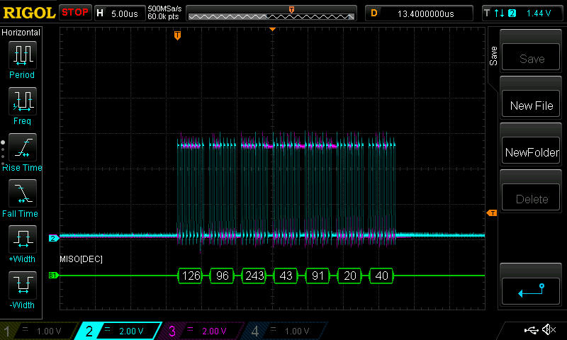
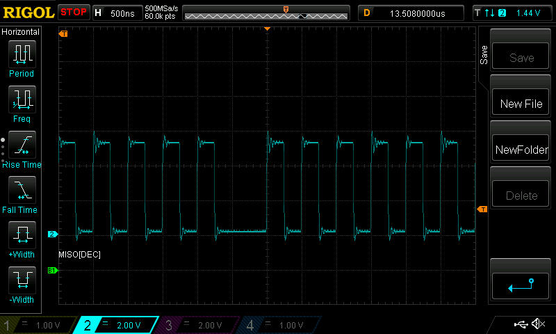
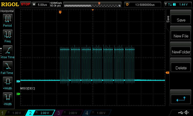
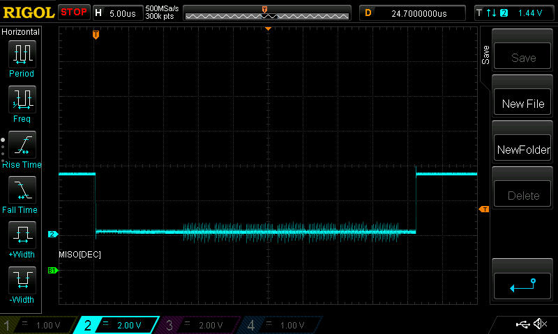
The tests located in the tests folder may be run under Python to test the correctness and functionality of python-periphery. Some tests require interactive probing (e.g. with an oscilloscope), the installation of a physical loopback, or the existence of a particular device on a bus. See the usage of each test for more details on the required setup.

License

python-periphery is MIT licensed. See the included LICENSE file.

python-periphery's People

Contributors

aussieseaweed avatar crazyivan359 avatar jakogut avatar sanketdg avatar ubiquitousthey avatar ukleinek avatar vsergeev avatar wallaceit avatar webmeister avatar

Stargazers

 avatar  avatar  avatar  avatar  avatar  avatar  avatar  avatar  avatar  avatar  avatar  avatar  avatar  avatar  avatar  avatar  avatar  avatar  avatar  avatar  avatar  avatar  avatar  avatar  avatar  avatar  avatar  avatar  avatar  avatar  avatar  avatar  avatar  avatar  avatar  avatar  avatar  avatar  avatar  avatar  avatar  avatar  avatar  avatar  avatar  avatar  avatar  avatar  avatar  avatar  avatar  avatar  avatar  avatar  avatar  avatar  avatar  avatar  avatar  avatar  avatar  avatar  avatar  avatar  avatar  avatar  avatar  avatar  avatar  avatar  avatar  avatar  avatar  avatar  avatar  avatar  avatar  avatar  avatar  avatar  avatar  avatar  avatar  avatar  avatar  avatar  avatar  avatar  avatar  avatar  avatar  avatar  avatar  avatar  avatar  avatar  avatar  avatar  avatar  avatar

Watchers

 avatar  avatar  avatar  avatar  avatar  avatar  avatar  avatar  avatar  avatar  avatar  avatar  avatar  avatar  avatar  avatar  avatar  avatar  avatar  avatar  avatar  avatar  avatar  avatar  avatar  avatar  avatar  avatar  avatar  avatar

python-periphery's Issues

Using Python Periphery for GPIO Pins

Hi! I am currently working with an UpBoard, which has multiple GPIO pins similar to a Raspberry Pi. I have three push buttons attached to three GPIO pins, and then a common ground. The circuit is really simple, but all of the elements are connected, and they read as False when the button is pushed, True otherwise. I tested this with an LED instead of my code, and it seemed to work fine. But when I run my code, even when no button is pressed it outputs as though one was. Any ideas why this could be?
`import time
import datetime
from periphery import GPIO
gpio_good_in = GPIO(26, "in")
gpio_neu_in = GPIO(6, "in")ย 
gpio_bad_in = GPIO(5, "in")

good_condi = gpio_good_in.read()
neu_condi = gpio_neu_in.read()ย ย 
bad_condi = gpio_bad_in.read()ย ย 
i= 1
while 1:ย 
if not good_condi:print(Feedback: Good)
elif not neu_condi:print(Feedback: Neutral)
elif not bad_condi:print(Feedback: Bad)
time.sleep(0.01)
i = i+1
gpio_good_in.close()ย 
gpio_neu_in.close()
gpio_bad_in.close()`

Question about PWM channel and pin

Here I was trying to use this library for the Coral EdgeTPU board, I'm having such difficulty to get the PWM to work. I have post a question here.

Here is my testing code:

from periphery import PWM
import time

# Open PWM channel 0, pin 0
pwm = PWM(0,0)

# Set frequency to 1 kHz
pwm.frequency = 50
# Set duty cycle to 75%
pwm.duty_cycle = 0.02

pwm.enable()

print(pwm.period)
print(pwm.frequency)
print(pwm.enabled)

# Change duty cycle to 50%

pwm.duty_cycle = 0.05

pwm.close()

Problem is this part:

# Open PWM channel 0, pin 0
pwm = PWM(0,0)

I can see output when running PWM(0,0) PWM(0,1) PWM(0,2)

but I get the error messsage when trying to run the following:

PWM(1,1)

PWM(2,2)

mendel@elusive-jet:/sys/class/pwm$ sudo python3 /usr/lib/python3/dist-packages/edgetpuvision/testPWM.py
OSError: [Errno 19] No such device

During handling of the above exception, another exception occurred:

Traceback (most recent call last):
  File "/usr/local/lib/python3.5/dist-packages/periphery/pwm.py", line 69, in _open
    f_export.write("%d\n" % pin)
OSError: [Errno 19] No such device

During handling of the above exception, another exception occurred:

Traceback (most recent call last):
  File "/usr/lib/python3/dist-packages/edgetpuvision/testPWM.py", line 5, in <module>
    pwm = PWM(1,1)
  File "/usr/local/lib/python3.5/dist-packages/periphery/pwm.py", line 44, in __init__
    self._open(channel, pin)
  File "/usr/local/lib/python3.5/dist-packages/periphery/pwm.py", line 71, in _open
    raise PWMError(e.errno, "Exporting PWM pin: " + e.strerror)
periphery.pwm.PWMError: [Errno 19] Exporting PWM pin: No such device

Based off the document from both Coral and the library site:
https://coral.withgoogle.com/tutorials/devboard-gpio/

https://github.com/vsergeev/python-periphery

The

PWM(1,1)

PWM(2,2)

should have worked without issue, I can see the following directories existed:

"\sys\class\pwm\pwmchip0"
"\sys\class\pwm\pwmchip1"
"\sys\class\pwm\pwmchip2"

In the python-periphery source code
https://github.com/vsergeev/python-periphery/blob/master/periphery/pwm.py

it should getting the path as following:

PWM(1,1) ===> /sys/class/pwm/pwmchip1/pwm1 if pwm1 not exists, then it should call the export to generate it.

So, My main question are:

  • What is channel and pin and how it is been used ?
  • Why I'm not able to get PWM(1,1) PWM(2,2) to work ?

Thank you in advance.

Example for using poll?

Do you have an example of using GPIO with poll? I'm trying to use this on an Intel Edison, have set edge to falling and no matter what parameter I pass to poll it always immediately returns with True, despite the state of the pin in question not having changed.

I can otherwise read and set pin states fine.

MMIO class cannot perform true 16-bit/32-bit accesses

mmio.py uses ctypes to read/write 16- and 32-bit quantities. Unfortunately, although common sense would be that those wrappers do real 16- and 32-bit loads and stores, that's not the case. The wrappers use memcpy, and worse, actually do read/modify/write for stores:

https://github.com/python/cpython/blob/12417ee0a6834cb874efd8061ca2d5172a0a9f42/Modules/_ctypes/cfield.c#L854

This breaks MMIO with registers that have side effects when read/written, and potentially breaks even worse on platforms where memcpy doesn't know how to coalesce writes and it ends up doing the write bytewise. mmio.py needs to find some other way to read/write registers that actually uses a single-instruction read or write.

GPIOError: [Errno 13] in conjunction with udev rules

I have setup udev rules so that i can run this library without root permissions. Im am using the library to access gpios.
In this environment the library throws an error, when i try to acess any gpio:

>>> gpio = GPIO(42)
periphery.gpio.GPIOError: [Errno 13] Setting GPIO direction: Permission denied

The cause for this is that after the device is exported it takes a moment until the udev rules get applied. However, this library is trying to change the direction for the GPIO right away. As the new udev defined permissions are not yet set, this fails with the aforementioned error.

To fix there error i monkey patched the _open function in the library, by adding a short sleep after the export:

## Monkey Patch for compatibility with udev rules
def _open(self, pin, direction):
    if not isinstance(pin, int):
        raise TypeError("Invalid pin type, should be integer.")
    if not isinstance(direction, str):
        raise TypeError("Invalid direction type, should be string.")
    if direction.lower() not in ["in", "out", "high", "low", "preserve"]:
        raise ValueError("Invalid direction, can be: \"in\", \"out\", \"high\", \"low\", \"preserve\".")

    gpio_path = "/sys/class/gpio/gpio%d" % pin

    if not os.path.isdir(gpio_path):
        # Export the pin
        try:
            with open("/sys/class/gpio/export", "w") as f_export:
                f_export.write("%d\n" % pin)
        except IOError as e:
            raise GPIOError(e.errno, "Exporting GPIO: " + e.strerror)

        # Loop until GPIO is exported
        exported = False
        for i in range(GPIO.GPIO_EXPORT_STAT_RETRIES):
            if os.path.isdir(gpio_path):
                exported = True
                break
            time.sleep(GPIO.GPIO_EXPORT_STAT_DELAY)

        if not exported:
            raise TimeoutError("Exporting GPIO: waiting for '%s' timed out" % gpio_path)
    
###   THIS IS THE NEW CODE ###############
    time.sleep(GPIO.GPIO_EXPORT_STAT_DELAY) 
#########################################################
    # Write direction, if it's not to be preserved
    direction = direction.lower()
    if direction != "preserve":
        try:
            with open("/sys/class/gpio/gpio%d/direction" % pin, "w") as f_direction:
                f_direction.write(direction + "\n")
        except IOError as e:
            raise GPIOError(e.errno, "Setting GPIO direction: " + e.strerror)
    # Open value
    try:
        self._fd = os.open("/sys/class/gpio/gpio%d/value" % pin, os.O_RDWR)
    except OSError as e:
        raise periphery.GPIOError(e.errno, "Opening GPIO: " + e.strerror)

    self._pin = pin

GPIO._open = _open

strange timestamp

Hey if i run the following script on Arm Cortex-A7 in a docker Container

from periphery import GPIO
from datetime import datetime
import time

all_gpio_list = []
c4l4 = GPIO("/dev/gpiochip4", 4, "in", edge="both")
all_gpio_list.append(c4l4)

while True:
    gpios = GPIO.poll_multiple(all_gpio_list, timeout=10)
    for gpio in gpios:
        event = gpio.read_event()
        print(event)
        print(datetime.now())
        print(time.time())

the output is:

EdgeEvent(edge='rising', timestamp=6212787543813)
2023-04-20 08:24:31.474127
1681979071.4748712

The timestamp of the event doesn't make any sense to me and I don't know how to convert it.
According to the documentation it should be a unix timestamp in nanoseconds.
So it should be something like this datetime.fromtimestamp(event.timestamp / 1000000) unfortunately it is not.

Do you have a hint for me?
Thanks in advance

i2c read API - add ability to specify starting address?

It seems that when reading from an i2c device, if you keep issuing the same "read", you get different data. What I have noticed is this:

  1. Start fresh, and open up the i2c device (i2c = I2C("/dev/i2c-0")
  2. Setup a new i2c.Message of 16 bytes, read=True
  3. issue the i2c.transfer
  4. read back the data
  • Excellent - I get the first 16 bytes from the i2c device specified at the device address I wanted
    Now, I want to read the first 16 bytes from the i2c device again.
    If I setup up a new i2c.Message of 16 bytes, read=True and issue the i2c.transfer again, I will actually get the NEXT 16 bytes of the i2c device, instead of the first 16 bytes. Even if I close the i2c (i2c.close()), and reopen it and start all over, I will get the next 16 bytes, and then the next, etc. Is there any way you can specify an offset at the i2c device address from which to read/write?

Data from consecutive packets are merged in serial module

Serial module. Data from consecutive packets are merged until the number of bytes specified in read is reached, or timeout is reached. This is wrong behavior, because when using native open/read/write system calls data is not messed up from consecutive packets. With this PR problem is solved: #28

Any plans to create a configurable cs_change in spi.py?

Hi!
It would be nice if there be any function or method to configurate spi_xfer.cs_change to 0 or 1.
My embedded board is supporting burst transfer in SPI and i need to create spi_xfer.cs_change=1 manually in transfer-function source always to use the normal mode.

GPIO pins fail to connect on first try on RaspberryPi

When initializing the pins on Raspbian, there appears to be a timing issue between the /sys/class/gpio/export and the write to /sys/class/gpio/direction

periphery/gpio.py

After running the code the first time the pin is added to the /sys/class/gpio/gpio{pin_number} list and therefore it works on the second try.

It looks like it could be addressed by adding a wait time if it fails. Here's a wrapper which addresses the issue:

for _ in range(number_of_attempts): try: gpio_pin = GPIO(pin, direction) break except GPIOError as e: if _+1 == number_of_attempts: raise e time.sleep(0.05) return gpio_pin

Bindings for MicroPython?

Cute project! I wonder, if you would be interested one of these days to develop further hardware API bindings for MicroPython on Linux: https://github.com/micropython/micropython-lib/tree/master/machine/machine . So far, only GPIO and timer support are implemented. MicroPython has slightly different API, but it's portable to various baremetal and RTOS boards. Quick overview of the API is: http://docs.micropython.org/en/latest/esp8266/esp8266/quickref.html#timers . Examples working across different types of boards: https://github.com/micropython/micropython/tree/master/examples/hwapi .

If you won't have time, I'll be glad to port your code myself some day, if you don't mind.

Thanks!

Frequency problems with PWM signals

Hey,

I am having an issues using the PWM code in Visual Studio Code (Python), I am using an Asus Tinker Edge R.
When I run the code, I can only use a frequency of 1Hz. All other values give "OSError: [Errno 22] Invalid argument", it does not matter if I set the frequency to 0.1 or to 1e3. The problem stays the same.
How can I fix this?

    from periphery import PWM
    
    Chip = 1        #Chip1, Channel0 is PWM pin 33
    Channel = 0
    
    pwm = PWM(Chip, Channel)  
    pwm.frequency = 1
    print('freq set')
    pwm.duty_cycle=0.5
    print('duty cycle set')
    pwm.enable()

With kind regards.

SPI transaction speed not meeting the maximum speed

Hi,

I am using SPI module in the library to handle SPI transactions from Raspberry PI CM4 to an onboard SPI device. The maximum speed is set to 5MHz on my script, and when I performed spi.transfer() of 7 bytes, the measurement time was well above the expected time.

I am trying to sample data at 38400SPS which is about 1 / 21us, but due to the delay of SPI transaction, I cannot actually achieve the sampling rate. I was wondering if you have any idea on how to increase the transaction speed of the SPI.

The following is my piece of code

spi = SPI("/dev/spidev6.1", mode = 1, max_speed = 5000000)
def read_data_bytes(spi, adc_type):
    if adc_type == 1:
        values = [RDATA1_OP] + [0xFF]*6
    else:
        values = [RDATA2_OP] + [0xFF]*6
    _logger.info(f'Sending Command = {values}')
    t1_start = perf_counter()
    values = spi.transfer(values)
    t1_stop= perf_counter()
    _logger.info(f'Reading ADC data= {values}, Tx time {t1_stop - t1_start}')
    return values
INFO:__main__:Reading ADC data= b'``\xf35{$b', Tx time 0.00021887299953959882
INFO:__main__:Data in decs = (96, 96, 243, 53, 123, 36, 98)

When scoped the MISO and Clock signal, I found out that the clock signal is not actually 5MHz, it's around 2MHz. And the CS is asserted much longer than it needs.

The following is captured image
clk_and_MISO
zoomed_in_clk
clk
CS

Do not write direction for SysfsGPIO if it is already set correctly

I want to read the state of a GPIO pin which is already exported in sysfs. Because SysfsGPIO always writes the direction, the GPIO is reset and the value I want to read is gone.

The CdevGPIO implementation checks if the direction is already set correctly. The same should be done with the SysfsGPIO implementation.

Duplicate writes using MMIO [Zynq / Yocto / Petalinux / Xilinx / ARM64]

I found on a Zynq device that python-periphery MMIO duplicated writes compared to using devmem. Any thoughts on why this could be? Does it have under the hood some kind of "retry" where it would perform the write twice? The device has a 64-bit ARM64 architecture (quad core A53 I believe).

https://forums.xilinx.com/t5/Processor-System-Design-and-AXI/axi-fifo-mm-s-AXI-FIFO-duplicates-words-requires-wrong-TX-length/m-p/1200351#M56397

About PWM class

GPIO class maintains open file descriptor as self._fd.
also I2C class maintains open file descriptor as self._fd.
but PWM class don't maintains open file descriptor of /sys/class/pwm/pwmchipX/pwmX,
and It open file Each method(period, frequency,polarity).
So It open /sys/class/pwm/pwmchipX/pwmX many times.
And never close file system.
Is this right?

[request] MicroPython support

For resource constrained devices, who often run OpenWrt which has MicroPython in its repo, this package would make a lot of sense since for example I2C and SPI are used a lot on those.

I've been trying to get the SPI code working on this, as a drop in replacement for machine.SPI, and need to make a couple adjustments since ctypes is missing a couple types, array has no buffer_info() and stuff like that. Also machine.SPI has several read and write functions, not just transfer.

It would be awesome to see the other peripherals ported as well.

Poll for multiple gpio edges

A static method to poll multiple GPIO objects for edges. Something like this:

@staticmethod
def poll_multiple(gpios, timeout):
    # Setup epoll
    p = select.epoll()
    for gpio in gpios:
        p.register(gpio._fd, select.EPOLLIN | select.EPOLLET | select.EPOLLPRI)

    p.poll(0)
    events = p.poll(timeout)
    print("events = %s" % repr(events))
    result = []
    gpio_fds_triggered = zip(*events)[0]
    for gpio in gpios:
        result.append(gpio._fd in gpio_fds_triggered)
    return result

Writing to an MMIO has no effect --- what do I the wrong way?

Hi @vsergeev

I'd power down USB0 PHY on an AM437x, so I was doing this as root from ipython console:
from periphery import MMIO
USB0_CTRL_MMIO = MMIO(0x44E10620, 0x1000)
hex(USB0_CTRL_MMIO.read32(0x00))
the last line gives output
0x3c186004
then I executed:
USB0_CTRL_MMIO.write32(0x00, USB0_CTRL_MMIO.read32(0x00) | 0x3)
but reading back
hex(USB0_CTRL_MMIO.read32(0x00))
gives the same:
0x3c186004
instead of
0x3c186007

Could you please help me, what do I the wrong way?

RE: More of a Thank You...

Hello,

First off, thank you for making this library. I have been able to use it w/ the BBAI from beagleboard.org.

...

Secondly, do not ever quit. B/c of you and this lib, I have been able to perform some basic .py file structures to light a LED on and off with PWM. Next, fading!

Seth

P.S. If you need to close the "issue," do so but remember I am thankful. I cannot wait to try out the rest of your ideas on the AI.

Control SPI chip select

I need to keep the SPI chip select asserted while transferring multiple messages (and doing some processing in between). The necessary low-level interface already exists (_CSpiIocTransfer.cs_change). Can this be made accessible from the high-level Python interface (i.e. SPI.transfer)?

Bias resistor kernel version check

So I learned yesterday that bias resistor settings are a recent addition to the Linux kernel (v5.5). In all my digging to get to the bottom of the ambiguous error 22s I was getting, I found out that ioctl calls to pinctrl should allow control of bias resistors (I have not looked into how yet).

I was going to implement kernel version checks and have my downstream software decide when to use this alternate method, but then I thought why do that when I can contribute it upstream to the library!

For the cdev class it will be pretty easy to add branching to use the alternate method if a bias setting is specified, but I wanted your input on how to do it for sysfs or if it should be done. My thought is just to add a named arg bias to the sysfs class init function. That would maintain backwards compatibility and not break the logic that counts unnamed args to determine if the user is trying to get a sysfs or cdev instance. What are you thoughts on this?

Edit: using pinctrl we could actually expand the sysfs class to offer all of the settings that cdev does with the exception of edge and label.

IIO support

As project getting close to hardware, there are multiple iio builtin drivers that python-periphery could support

LED triggers support

Please consider adding support for some led triggers like gpio, timer.
This would be very useful, because for example it will provide a way to blink led within system kernel, not userland software.

Callback on interupt and adc

Hi!

Maybe I'm missing something but I've been using libmraa (on 4.4 kernel) but since I now want to use 5.x I'm looking for a replacement. Your project looks nice but I have a few questions, in mraa I used a callback for an interrupt like this:

import mraa
import time

def callback(userdata):
    print ("interrupt triggered with userdata=", userdata)

pin = mraa.Gpio(23)
pin.dir(mraa.DIR_IN)
pin.isr(mraa.EDGE_BOTH, callback, None)

while(True):
    time.sleep(5)
    print("5s loop")
    # simply wait for interrupt

but if I understand correctly I now need to poll in the while loop, correct?

import sys, time
from periphery import GPIO

gpio_in = GPIO("/dev/gpiochip1", 24, "in", edge="both")

try:
  while True:
    if gpio_in.poll(0.1):
      print(gpio_in.read_event())
except KeyboardInterrupt:
  gpio_in.close()
  sys.exit(130)

I also need to read the ADC pin (Rock Pi S), is that something you might implement in the future?

Thanks for your great work!

Using PWM on two instances

I have a very strange use case for this library such that I need two instances accessing the same PWM at the same time. I am aware this is not very typical or recommended. Because one PWM instance can close the file for another PWM instance using the same PWM and thus the same file, if we lose reference to one PWM instance and thus close the file, the other PWM instance will fail as well.

To combat this and to make sure that the other PWM instance can keep going even if one stops and closes the file, we can detect for a FileNotFoundError or PWMError and restart the PWM instance for the one that is intended to keep going. However, I am unsure why this first script does not work for that, but the second script does. The behavior of the first script is that it will keep throwing an error (either FileNotFoundError or PWMError) if another PWM instance stops, closing the file. It never recovers from this. However, the second script will throw the error once and then self-recover, which is intended. I am curious as to why the first script works, and the second script does not.

To reproduce this, start one of each script below and have them fun simultaneously. If you stop the first one first via a KeyboardInterrupt, the second one will throw an error and keep going. This is good. However, if you stop the second one first, the first one will continuously throw an error and does not recover.

Script that does not work:

import time
import random
import traceback

from periphery import PWM, PWMError

class Script():

    def __init__(self):
        self.pwm = PWM(0, 1)

    def start(self):
        while True:
            desired_frequency = random.uniform(1000.0, 10000.0)
            try:
                self.pwm.frequency = desired_frequency
                output = self.pwm.frequency
            except (PWMError, FileNotFoundError):
                print(traceback.format_exc())
                self.pwm = None
                self.pwm = PWM(0, 1)
            else:
                print(f"Frequency = {output}")

            time.sleep(0.1)

if __name__ == "__main__":
    script = Script()
    script.start()

Script that works:

import time
import random
import traceback

from periphery import PWM, PWMError

class Script():

    def __init__(self):
        self.retry = True

    def start(self):
        while True:
            desired_frequency = random.uniform(1000.0, 10000.0)
            try:
                if self.retry:
                    self.pwm = None
                    self.pwm = PWM(0, 1)
                    self.retry = False

                self.pwm.frequency = desired_frequency
                output = self.pwm.frequency
            except (PWMError, FileNotFoundError):
                print(traceback.format_exc())
                self.retry = True
            else:
                print(f"Frequency = {output}")

            time.sleep(0.1)

if __name__ == "__main__":
    script = Script()
    script.start()

PWM doesn't wait for udev to apply permissions after export

After exporting PWM udev will trigger and if rules are set up correctly non-root permissions will be applied.
This process isn't synchronous, i.e. it will take some time after export until the sysfs node can be used by non-root users.

gpio.py has retry logic to account for this:
https://github.com/vsergeev/python-periphery/blob/master/periphery/gpio.py#L723

pwm.py however does not. The following test case shows this

from periphery import PWM
import time

# Exports the PWM, this succeeds because udev set permissions correctly.
pwm = PWM(0, 0)

# Tries to write to /sys/class/pwm/pwmchip0/pwm0/period
# This fails with:
# "PermissionError: [Errno 13] Permission denied: '/sys/class/pwm/pwmchip0/pwm0/period'"
# even if udev have set permissions correctly.
try:
	pwm.frequency = 1e3
	print('test1: frequency set')
except Exception as e:
	print('test1: failed to set frequency', e)
pwm.close()

# Now add a small delay and try again.
pwm = PWM(0, 0)
time.sleep(0.1)
pwm.frequency = 1e3
print('test2: frequency set')

time.sleep(5)
pwm.close()

Output as non-root:

test1: failed to set frequency [Errno 13] Permission denied: '/sys/class/pwm/pwmchip0/pwm0/period'
test2: frequency set

With suggested fix:

test1: frequency set
test2: frequency set

If, with the suggested fix, there's a real issue with permissions the following is raised in PWM._open:

periphery.pwm.PWMError: [Errno 13] Permission denied: /sys/class/pwm/pwmchip0/pwm0/period

gpio not unexported on close

Hi
periphery export the gpio correctly on open
try:
with open("/sys/class/gpio/export", "w") as f_export:
f_export.write("%d\n" % pin)
except IOError as e:
raise GPIOError(e.errno, "Exporting GPIO: " + e.strerror)

but on close it didn't unexport the pin

Coral dev board download problem

I download on dev board : sudo pip3 install python-periphery

Get this error : Retrying (Retry(total=0, connect=None, read=None, redirect=None, status=None)) after connection broken by 'NewConnectionError('<urllib3.connection.VerifiedHTTPSConnection object at 0xffffaeeab4e0>: Failed to establish a new connection: [Errno -3] Temporary failure in name resolution')': /simple/python-periphery/
Could not find a version that satisfies the requirement python-periphery (from versions: )
No matching distribution found for python-periphery

Can you please explain more regarding I2C?

Hello,
your library looks really cool.
However I was trying to use it for I2C and could not understand the logic behind that code.
There are 3 entities involved in I2C operations: the device address, the register within that device, and the value that we want to write or read to the register.

How do you accomplish a writing of value into a register? and how do you read the value from a register?

Thank you!
-Itay

Polling techniques seems a bit inaccurate for sysfs

    def poll(self, timeout=None):
        if not isinstance(timeout, (int, float, type(None))):
            raise TypeError("Invalid timeout type, should be integer, float, or None.")

        # Setup poll
        p = select.poll()
        p.register(self._fd, select.POLLPRI | select.POLLERR)

        # Scale timeout to milliseconds
        if isinstance(timeout, (int, float)) and timeout > 0:
            timeout *= 1000

        # Poll
        events = p.poll(timeout)

        # If GPIO edge interrupt occurred
        if events:
            # Rewind
            try:
                os.lseek(self._fd, 0, os.SEEK_SET)
            except OSError as e:
                raise GPIOError(e.errno, "Rewinding GPIO: " + e.strerror)

            return True

        return False

minor -> the timeout should be divided by 1000 not multiplied to convert sec to millisec as select.poll.poll is expecting in second

major:
the events are returned as a bitmap that needs to be deciphered probably in a if else kind of state (as we are having or on 2 events). if an error occurs we should return false.

Not sure about this: but i think this part of the code should use https://man7.org/linux/man-pages/man7/inotify.7.html. to detect changes to the files and based on the edge set, it should return true or false. if we can discuss this and come to a solution, will like to code contribute this part.

Spi - Chip select deactivates

Hi, I'm trying to use your code to talk across the spidev bus through python on an Arm7 processor. Using your code the spi bus deactivates the chip select after each write but the device I'm writing to needs the chip select to be active through the response. Is this an issue you have run into or have any suggestions on how to implement?

GPIO polling issues

I am trying to use python-periphery to poll a gpio pin on an Arduino Portenta x8 running Ubuntu 22.04.1 LTS.

I am trying out the most basic polling:

from periphery import GPIO

gpio0 = GPIO("/dev/gpiochip5", 0, "in", edge="both")
if gpio0.poll():
  print(gpio0.read_event())

However, the poll function seems to never return regardless of any signals I send to the pin. I'm not sure whether there's some other setup I might be missing, any ideas on what I can try to fix this or debug this would be great! Prior to setting up any polling, the gpio read functions work (reads True when signal is high and False when low).

Another possibly related issue is that upon setting the edge type for a pin (gpio.edge = "both", for example), upon calling the read() function on that pin (gpio.read()), I get this error:

Traceback (most recent call last):
  File "/usr/local/lib/python3.10/dist-packages/periphery/gpio_cdev1.py", line 323, in read
    fcntl.ioctl(self._line_fd, Cdev1GPIO._GPIOHANDLE_GET_LINE_VALUES_IOCTL, data)
TimeoutError: [Errno 110] Connection timed out

During handling of the above exception, another exception occurred:

Traceback (most recent call last):
  File "/home/dev/wall_panels/bb_ws/src/spc_unit_tester/spc_unit_tester/poll_test.py", line 6, in <module>
    value0 = int(gpio0.read())
  File "/usr/local/lib/python3.10/dist-packages/periphery/gpio_cdev1.py", line 325, in read
    raise GPIOError(e.errno, "Getting line value: " + e.strerror)
periphery.gpio.GPIOError: [Errno 110] Getting line value: Connection timed out

I've also noticed this Errno 110 in other instances, but this is one way I've found to consistently reproduce it. So far the only way I know to regain use of the pin after this is to restart my board, so any help with this would be appreciated, thanks!

Add typing files

So I'm switching over to pylance in a project I'm working on that uses periphery and I've made a pyi file for the gpio file. I figured I'd share it here for anyone interested in making them for the rest of this library. If I have time I may come back around and do them, but I'm not sure when that would be.

I had to change the file extension in order to upload it: gpio.txt
12/12/2020 updated EdgeEvent properties

Calling method directly doesn't alter character device

I've been doing some experimenting with GPIO access via docker so I can prep docs compatible with arm64 versions of the official octoprint/octoprint docker image.

I've got a small test script that I'm using that will allow me to test permissions and devices for the docker container, however, I've run into a problem of sorts.

If I write a method that utilizes GPIO, and then immediately execute it, the python process thinks the character device state has been altered, but it's not actually changing.

However, if my method returns the object and then my script calls that, it works.

Here's the repo I'm working with, that has a tiny example: https://github.com/LongLiveCHIEF/docker-pi-gpio/tree/ec2fb5680078d081feaf5994fa7a42fc5113fe1e

i have a method called LED, which does this:

Calling approach 1 (this works)

def LED(chip, pin):
    led = GPIO(chip, pin, "out")
    return led

# then call it from tests/on.test.py
led = dockergpio.LED("/dev/gpiochip0", 17)
led.write(True)

Calling approach 2 (this does not work)

def ledOn(chip, pin):
    led = GPIO(chip, pin, "out")
    led.write(True)

# then call it from tests/gpio.test.py
dockergpio.ledOn("/dev/gpiochip0", 17)

No errors are thrown, it's just that the led lights up using the first approach, but does not light up using the 2nd. I'm not changing anything with the hardware setup or environment in between executing the two tests.

What's interesting, is that if I add print(led.read()) to the body of the second approach, both before and after writing the state, the first read prints False, but the second read returns True.

Why would the first approach work, but not the second? The only thing I can think of is that the second approach closes the file descriptor immediately after using it.

I haven't yet hooked up the scope for the second approach to do a capture trigger on a rising edge to see if the voltage actually changed for a small time.

I'm new to python, so forgive me if this is something with scope/instantiation that would be obvious to a seasoned python programmer.

gpio: doesn't work for named gpios

Hello,

running periphery on an Arietta G25:

root@arietta:~# python3 -c "from periphery import GPIO; GPIO(45, 'high')"
Traceback (most recent call last):
  File "<string>", line 1, in <module>
  File "/usr/lib/python3/dist-packages/periphery/gpio.py", line 43, in __init__
     self._open(pin, direction)
  File "/usr/lib/python3/dist-packages/periphery/gpio.py", line 82, in _open
    raise TimeoutError("Exporting GPIO: waiting for '%s' timed out" % gpio_path)
TimeoutError: Exporting GPIO: waiting for '/sys/class/gpio/gpio45' timed out

This fails because the gpio directory appears with the name pioB13. That's because the driver sets names for the gpiochip in the kernel. See https://git.kernel.org/pub/scm/linux/kernel/git/torvalds/linux.git/tree/drivers/pinctrl/pinctrl-at91.c#n1896

I don't know how this can be (easily) handled in periphery, probably the sanest approach is to use /dev/gpioctl instead of the (deprecated) /sys/class/gpio approach.

__enter__() should return self

Current implementation (e.g. in gpio.py):

def __enter__(self):
    pass

Ideally should be

def __enter__(self):
    return self

to make the following example working:

with GPIO(10, "out") as pin:
     pin.write(True)

Errno 1 Operation not permitted

This may not be an issue with periphery itself, but I'm hoping for some help in diagnosing a problem that currently has me stumped.

If I strip my code down the basics, I end up with the follow, that works:

from periphery import GPIO
import multiprocessing as mproc
from time import sleep

def proc1():
  p2=GPIO("/dev/gpiochip0", 2, "in")
  p1=GPIO("/dev/gpiochip0", 1, "out")
  p1.write(True)
  sleep(2)
  p1.write(False)
  p1.close()
  p2.close():

mproc.Process(target=proc).start()

My actual program is more complicated obviously, but at its core I have the same thing happening. A process forked from the main process accessing multiple pins. I can open the pins no problem, I can read all of them no problem, but I get errors when I try to call write on the GPIO instance.

Test and program run using sudo python3 so permissions shouldn't be an issue. I also tried running python3 directly as root using sudo -i but no change.

I have different results on different hardware, currently I have an RPi3B and an Orange Pi Zero LTS.

  • RPi throws err 22 Invalid argument.
  • OPi thorws err 1 Operation not permitted.

Any pointers on where to look or how to get more debug information would be most appreciated. For reference, I am working on switching MQTTany over to cdev gpio access and found this library to be the best option. The branch is private, but if you are willing to dig that deep into it, I can publish it.

Recommend Projects

  • React photo React

    A declarative, efficient, and flexible JavaScript library for building user interfaces.

  • Vue.js photo Vue.js

    ๐Ÿ–– Vue.js is a progressive, incrementally-adoptable JavaScript framework for building UI on the web.

  • Typescript photo Typescript

    TypeScript is a superset of JavaScript that compiles to clean JavaScript output.

  • TensorFlow photo TensorFlow

    An Open Source Machine Learning Framework for Everyone

  • Django photo Django

    The Web framework for perfectionists with deadlines.

  • D3 photo D3

    Bring data to life with SVG, Canvas and HTML. ๐Ÿ“Š๐Ÿ“ˆ๐ŸŽ‰

Recommend Topics

  • javascript

    JavaScript (JS) is a lightweight interpreted programming language with first-class functions.

  • web

    Some thing interesting about web. New door for the world.

  • server

    A server is a program made to process requests and deliver data to clients.

  • Machine learning

    Machine learning is a way of modeling and interpreting data that allows a piece of software to respond intelligently.

  • Game

    Some thing interesting about game, make everyone happy.

Recommend Org

  • Facebook photo Facebook

    We are working to build community through open source technology. NB: members must have two-factor auth.

  • Microsoft photo Microsoft

    Open source projects and samples from Microsoft.

  • Google photo Google

    Google โค๏ธ Open Source for everyone.

  • D3 photo D3

    Data-Driven Documents codes.