taligentx / dsckeybusinterface Goto Github PK
View Code? Open in Web Editor NEWAn Arduino/esp8266/esp32 library to directly interface with DSC security systems.
License: GNU General Public License v3.0
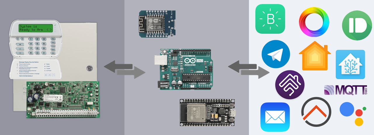
An Arduino/esp8266/esp32 library to directly interface with DSC security systems.
License: GNU General Public License v3.0


GREAT WORK!
Did anyone found the way to also act as a zone expander? Would be very nice to add "virtual" sensors or zones. I couldn't find any reference/information on how zones expanders work. If someone has any guess we might work on it! Thanks in advance.
Hello,
QR codes cannot be scanned nor parsed as an image from gallery. Hovering display just never scans it, opening as an image directly - blynk app errors: Not a valid blynk QR code.
Not sure if it is app issue or QR code itself. Tested using newest blynk app from google market on Android device.
@taligentx, can we get the user id from panel? Is it possible?
For example,
1)In panel we program user1 have code 0001, user2 have code 0002.
2)when panel is armed/disarmed access code entered
Can we by entered code or other data determinate which user armed/disarmed panel?
On real keypad entered code 0001 - we get user1, entered code 0002 - we get user2 in sketch.
@taligentx
In the last release when you added the support for Zone B - Section 9-16 the sections are continuously reported - Zone restored: 9
Info: My alarm system has an expansion card for additional 8 sections (9-16)
Log_PowerSerie832_PC5015-ContinuesRestoredZone-9_KeybusReader.txt
Log_PowerSerie832_PC5015-ContinuousRestoredZone-9_Status.txt
Hello
some additional data for DSC PC1565 panel.
4704.33: 00010110 0 00001110 00100010 11100110 00101100 [0x16] Unknown panel | Zone wiring: EOL | *8 programming
also in installation mode in section [903] Module Supervision Field:
19035.68: 00000101 0 10000001 11101111 10010001 11000111 [0x05] Partition 1: Ready Backlight - Unrecognized data: 0xEF | Partition 2: disabled
19035.75: 00001010 0 10000001 11101111 01000001 00000000 00000000 00000000 00000000 10111011 [0x0A] Ready Backlight - Unrecognized data: 0xEF | Zone lights: 1 7
br
Zahari
hi, i have DSC PC 585H, i want to see earlier triggered zones using *3 command, dsc panel showing all triggered zones, but in blynk i cannot use this option, what problem is?
i recorded short video:
video_2019-06-27_23-13-02.zip
or link: https://mega.nz/#!zLgznQTQ!Xzg2BpokUwbx3Bfl6CICvpI61P3mmWkPqjwGZnMO6D4
Post logs here as captured by the KeybusReader example for the missing data listed below. In KeybusReader, set dsc.hideKeypadDigits = true; to keep access codes typed in to the panel obscured for posting publicly.
Changes:
Great work!! Have done some initial test using the Arduino Status Sketch on NodeMCU, there is no status ArmedStay detected only Exit delay in progress and Partition disarmed
Alarm system - PowerSerie 832 - PC5015 - Panel LCD5500
Log_powerSerie832_PC5015-NoArmedStayDetection_KeybusReader.txt
Log_powerSerie832_PC5015-NoArmedStayDetection_Status.txt
I'm a little bit confused regarding esp8266 pins to use since there is a difference in sketches vs. decriptions.
According to your description the following pins shall be used (esp8266: D1,D2,D8), but in the Status and KeybusReader sketch D9 is used!
In Status and Keybus Reader sketch
#define dscClockPin 3 //esp8266 v1.0 D9
#define dscReadPin 4 //esp8266 v1.0 D2
#define dscWritePin 5 //esp8266 v1.0 D1
In Status-MQTT-Homebridge sketch
#define dscClockPin D1
#define dscReadPin D2
#define dscWritePin D8
also - I assume it is possible to define either Dx or GPIOx, example GPIO 5 or D1
Hello! How I can stop dscKeybusInterface? I use nodemcu v3 I want to use OTA, but when my writePIN konnected to the GREEN key-bus wire I can't do OTA, it starts and failed. I my sketch without dsc.start(), keeping all wires connected to panel - ota work fine. Any ideas about it? I use last SDK & Core.
I have tried to use the ESP8266 HomeAssistant-MQTT.ino and tried to connect it with OpenHab. It did not work out, I do not know why.. Would it be a lot of work to make an example code for OpenHab through MQTT?
Hi Thanks for all your work. I am not been successful cloning the QR code, I get an error message saying "Not Valid Blynk Code" when I download or try from screen the following file you provided https://user-images.githubusercontent.com/12835671/42364287-41ca6662-80c0-11e8-85e7-d579b542568d.png
Thanks for your help.
Apologies for opening a new issue, but I thought you would be interested too see this. Please feel free to close this issue.
https://github.com/sixerdoodle/DSCWIRELESSKEYPAD
http://www.jenrathbun.com/Electronics/projects/tricks-with-google-home/wireless-dsc-pc1555-keypad/
It also makes use of two PINS, one read and one write on the microcontroller side, but the circuit looks a bit different:

Hi, on a serial console I am observing soft WDT reset periodically, there are some articles in the net about it, eg. esp8266/Arduino#2866 which suggests issues with watchdog timer, but I don't know how to identify relevant code line for this. Any hints?
08:57:47.938 ->
WiFi connected: 192.168.1.41
08:57:48.963 -> MQTT connected: 192.168.1.30
08:57:48.963 -> DSC Keybus Interface is online.
08:59:35.135 -> Soft WDT reset
08:59:35.135 ->
08:59:35.135 -> ctx: cont
08:59:35.135 -> sp: 3ffefaf0 end: 3ffefd90 offset: 01b0
08:59:35.135 ->
08:59:35.135 -> >>>stack>>>
08:59:35.135 -> 3ffefca0: 00000007 3ffee738 3ffee610 40203ac0
08:59:35.168 -> 3ffefcb0: 3ffefcf0 3ffee610 00000000 40201ddf
08:59:35.168 -> 3ffefcc0: 3ffefcf0 00019a44 3ffee738 402051f4
08:59:35.168 -> 3ffefcd0: 00000000 3fffdad0 3ffee738 402035f2
08:59:35.168 -> 3ffefce0: 2f637364 00746553 3ffee738 40203508
08:59:35.168 -> 3ffefcf0: 514d0401 00000001 3ffe8775 3ffee73c
08:59:35.168 -> 3ffefd00: 3ffe84b4 00000000 3ffee738 40203456
08:59:35.168 -> 3ffefd10: 3fffdad0 0000001f 3ffeed3c 3ffefd40
08:59:35.204 -> 3ffefd20: 3fffdad0 00000001 3ffee738 40201f46
08:59:35.204 -> 3ffefd30: 3fffdad0 00000000 3ffeed60 40201fa8
08:59:35.204 -> 3ffefd40: 3fffdad0 3ffee80c 3ffeed3c 40204d74
08:59:35.204 -> 3ffefd50: 3fffdad0 3ffee80c 3ffeed3c 4020236c
08:59:35.204 -> 3ffefd60: 00000000 00000000 00000001 3ffeed68
08:59:35.238 -> 3ffefd70: 3fffdad0 00000000 3ffeed60 4020501c
08:59:35.238 -> 3ffefd80: feefeffe feefeffe 3ffeed70 40100718
08:59:35.238 -> <<<stack<<<
08:59:35.272 -> ets Jan 8 2013,rst cause:2, boot mode:(3,6)
08:59:35.272 ->
08:59:35.272 -> load 0x4010f000, len 1384, room 16
08:59:35.272 -> tail 8
08:59:35.272 -> chksum 0x2d
08:59:35.272 -> csum 0x2d
08:59:35.272 -> v3ffe88b0
08:59:35.272 -> ~ld
08:59:35.505 ->
WiFi connected: 192.168.1.41
08:59:36.516 -> MQTT connected: 192.168.1.30
08:59:36.516 -> DSC Keybus Interface is online.
update
in tests I identified moment when it happens - each time when I try to send 1A over MQTT
The esp8266 sketches broadcast a unsecured network / SSID (Example: ESP_123456). This behaviour can and should probably be disabled by using WiFi.mode(WIFI_STA); in the setup routine of the sketch.
Example:
...
  WiFi.begin(wifiSSID, wifiPassword);
  WiFi.mode(WIFI_STA);
  while (WiFi.status() != WL_CONNECTED) delay(500);
...
Only one zone is reported in alarm state, its seems it's only the first tripped zone that is reported
Partition armed away
Zone open: 9
05/17/2018 16:06 | Zone alarm: 9
05/17/2018 16:06 | Partition in alarm
Zone open: 7                              // Zone configured as door entrance delay
Zone restored: 7
Zone open: 1                              // Motion detection - sholud also be Zone alarm state ??
Zone open: 2                              // Motion detection - sholud also be Zone alarm state ??
Zone restored: 1
Zone open: 5                              // Motion detection - sholud also be Zone alarm state ??
Zone restored: 2
Zone open: 2
Zone open: 1
Zone restored: 5
Partition disarmed
Zone restored: 1
Zone restored: 2
05/17/2018 16:07 | Zone alarm restored: 9
Zone open: 7
Zone restored: 9
Log_PowerSerie832_PC5015-ALARM_OnlyOneZone_Status.txt
Log_PowerSerie832_PC5015-ALARM_OnlyOneZone_KeybusReader.txt
Hi,
I'm trying to scan Blync code on my Android (A5 2016) and I have probles as image is very dark itself and when trying to scan from the monitor it is hardly visible, phone doesn't capture it at all.
When I try to download image and open it with Blync it says - not valid QR code.
How did you solve this issue?
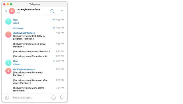
Hi, no one tried to use this library with the Telegram bot to control the alarm and receive the event?
I want to try, but not knowing where to start ... I am not very good at programming.
It's been over 6 months I interfaced POWER1864 all works like a charm. But occasionally mqttPartitionTopic topic stays "pending" and "armed_home" or "armed_away" is not published when panel is armed. Never faced problem with disarming.
runs on old arduino leonardo+eth shield.
Anyone experienced the same issue?
For some reason I am able to arm/disarm (write to panel) via Homeassistant and Homebridge, but nothing seems to be coming into the dsc/Get/ZoneX/# mqtt topics (reading from panel then posting to these zone topics), for zone status... Do you maybe have any idea...?
Further testing seems that the Arduino reads the incoming messages in the dsc/Set topic fine. It then successfully executes the panel "A", "S" and "D" commands, but never posts the status back to the dsc/Get topic so that armed status can be read by Homeassistant/Homebridge. The same goes for the dsc/Get/ZoneX topics. The Arduino does not publish zone updates there. I am testing with the sketch in pull request: #15
Hi,
Same problem on this sketch like in esp. Serial not didn`t see zones 17-32 and maybe up to 64. Probably the problem is in dscKeybusInterface.h ? Tested on pc5020 and 32 zones.
Hi, sorry for my English, I'm using the google translator. I wanted to try "Web virtual keypad", but it doesn't work for me in the browser. I compile the program, but it doesn't work for me, in serial print it shows me
"........
WiFi connected
192.168.1.44
" and nothing more.
I have doubts if the libraries are being loaded correctly since in the IDE it shows me some in black, I enclose sending captures.


Hi,
running the esp MQTT example, I have noticed whenever the motion detectors trigger, the mqttPartitionTopic receives multiple D events (I think 4 D's per trigger). Unsure if this is the intended behaviour of the panel, dsc software or MQTT sketch ?
PS: this is from closed issue #89
mosquitto_sub -t home/dsc/Get/Zone3
0
1
0

1
0
1
0

1
0
mosquitto_sub  -t home/dsc/Get/Partition1
D
D
D
D
D
D
D

D
D
D
D
D
D
D
D
D

D
D
D
D

D
D
D
D

D

D
D
D
D
Hi,
I'm using an arduino Uno for this, but after a long time (weeks if not months) it seems unresponsive and the only way to recover is to restart it with power recycle.
Is it possible that dsc.handlePanel(); never returns? I put it into my loop, but loop does not seem working any more.
Good morning
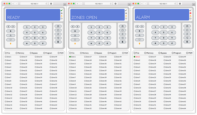
I have (almost) successfully implemented HTTP Server example. Virtual keypad reads all messages and numeric buttons also write back into the key bus, however all the other "combo" buttons (stay arm, arm, etc. ) do not work.
When you press those buttons , it beeps on the virtual keypad and the serial output only sends open/close braces {}.
I have a PC1616 system
Thanks!
Ok someone had to request this! I’ve been reading in the reference manual about keypad lockout and I can’t figure out if there’s a way to find out if it is enabled, obviously without the installer code.
So I am curious about the suggestion you make about the workaround:
...possibly automatically power-cycling the panel with a relay to skip the lockout time.
That would require knowing that a keypad lockout happened, and an event will be registered, but why do you think that it isn’t saved even if the unit power cycles?
Hello,
first, amazing work, thank you !
I have just connected my module and ran the reader sketch, I get lot's of things working but notice these two unrecognized data that I found you referenced in the below linked issue comment. Those two events seem to repeat few times during the time I connected the module I built.
FYI: my panel is connected to a monitoring company using cellular connection, has 9 zones (?) and panel model is RFK5500-433 (supports wireless RC).
I will send the entire log file if there's another run you require to debug this. Thank you again :)
  433.47: 11100110 0 00011010 01000000 00000000 00000000 00000001 00000001 00000000 00000000 01000010 [0xE6] 0x1A: Unrecognized data
  433.47: 11111111 1 11111111 11111111 11111111 11111111 11111111 11111111 11111111 11111111 10000000 [Keypad] Unrecognized key: 0xFF

...
  433.57: 11001110 0 00000001 00010000 00000000 00000000 00000000 11011111 [0xCE] Unrecognized data
  433.63: 11001110 0 01000000 11111111 11111111 11111111 11111111 00001010 [0xCE] Partition 1,2 activity
There are some other "errors":
  225.67: 00010110 0 00001110 01000001 11110101 01011010 [0x16] Unknown panel | Zone wiring: NC | Interval 4m
  191.06: 11111111 1 11111111 11111111 11111110 11111111 11111111 11111111 11111111 11111111 [Keypad] Unknown Keybus notification
I've mostly decoded 0xE6 and 0xEB and have pushed a new develop branch for feedback and testing, supporting partitions 2-8, zones 33-64, and writing to partitions 1 and 2.
...
Originally posted by @taligentx in #2 (comment)
At first I want to thank for this work. It's exactly what I was looking for.
My alarm has 20 active zones and I found that zones over 16 were not working. After a little debugging I found a bug in the dscKeybusProcessData.cpp file.
In "processPanel_0x34()" where the panelData should be written to zones 17-24, the data are written to zones 9-16. Exactly the same happens with zones 25-32.
To solve this you must modify line 336
openZones[1] = panelData[6];
with
openZones**[2]** = panelData[6];
and line 359:
openZones[1] = panelData[6];
with
openZones**[3]** = panelData[6];
After that all seems to work OK.
Hi,
I sent the included pcb files in the download to a manufacturer. They came back and said they cant use the files, they need the Gerber and Ascii drill files. Any chance this is available and can be sent to me please?


Zone 9 in alarm state but not reported in status sketch (dsc.alarmZonesChanged)
Exit delay in progress
Zone open: 7
Zone restored: 7
Partition armed away
Zone open: 9        // Zone alarm state
05/09/2018 19:00 | Partition in alarm
Zone open: 7       // Entrance door, delayed
Partition disarmed
05/09/2018 19:00 | Zone alarm restored: 9
Zone restored: 7
Zone restored: 9
Log_PowerSerie832_PC5015-ALARM_zone9_KeybusReader.txt
Log_PowerSerie832_PC5015-ALARM_zone9_Status.txt
Hi @taligentx ,
I upload sketch with pushbullet (change only messages to my language). It works, but i need a little more notification to add ( alarm armed, alarm disarmed, arm AWAY, arm STAY, sabotage zones. I try to add this messages, but did not work. I do not know how to add this notification properly. I try only copy paste from yours sketch and change values.
I add it like this but no working, sketch comile without problem
   if (dsc.armed[partition]) {
    dsc.armed[partition] = false;  //

    char pushMessage[42] = "Armed partycja ";
    char partitionNumber[2];
    itoa(partition + 1, partitionNumber, 10);
    strcat(pushMessage, partitionNumber);

    if (dsc.armedChanged[partition]) sendPush(pushMessage);
    else sendPush("Dissarmed");
   }

    if (dsc.armedAway[partition]) {
    dsc.armedAway[partition] = false;  //

    char pushMessage[44] = "AWAY ";
    char partitionNumber[2];
    itoa(partition + 1, partitionNumber, 10);
    strcat(pushMessage, partitionNumber);

    if (dsc.armedStay[partition]) sendPush(pushMessage);
    else sendPush("STAY");
   }
The next question is possible add a notification of 24 hours waterflow line, 24 hours gas line, etc.?
Edit:
I see another problem with sketch. When i lost AC power and get it again, i don`t see pushbullet notification? It works only when alarm is armed?
Hi there,
Is there is a way to stop dscKeybusInterface?
I mean, like dsc.begin but dsc.stop
I am integrating the code with a different Wifi manager (IoTWebconf instead of WiFiManager) and for some reason (that I don´t know) if dscKeybusInterface is started, it fails to connect to WiFi.
So I workarounded starting dscKeybusInterface after Wifi connection is stablished.
if (iotWebConf.getState() == IOTWEBCONF_STATE_ONLINE) {
                if (!DSCBegined){
                    // Starts the Keybus interface and optionally specifies how to print data.
                    // begin() sets Serial by default and can accept a different stream: begin(Serial1), etc.
                    dsc.begin();
                    DSCBegined = true;
                    Serial.println(F("DSC Keybus Interface is online."));
                }
        doDSC();
      }
And then it´s work fine, but if Wifi connection is lost, it will retry connecting with no success because dscKeybusInterface is begined. So I need stop dscKeybusInterface until Wifi connection is restablished and then dsc.begin again.
Can anyone suggest a way to do this?
Thanks in advance for your sugestions.
Best regards.
Hello!
It's more feature request: could HASS sketch be modified to send pereodical status update to MQTT? Cause you will loose control from "alarm control panel" if HASS will be restarted after power failure (so no arm/disarm buttons).
P.S. 1:
Confirming work on PC1565
P.S. 2:
Also for Wemos D1 R1 (!) actual pins are:
D3 (5), D4 (4), D10 (15)
and board can be powered directly from AUX via Vin
P.S. 3:
what is meaning of 1kOhm resistor in connection scheme to transistor? It's also working without it (accidentally forgotten to add it when was rewiring)
Hi,
I would like to redirect the dscKeybusReader so I can send the print data to whatever output device: serial, file, IP (MQTT, syslog,...)
I know very little of C++, but I managed to get that stream inherits from print class, and dsc.begin sets stream output to Serial. Is there an easy way to redirect the stream to a buffer that can be accessed by a method to direct the print data to the appropriate output device?
What I have done so far is to add a new method and did a global and replace for stream->print with the new method, but realize there must be a cleaner OO way to do this. Any suggestions? Ideally the object/buffer should be accessible in the sketch so the user has control over it and use the “output” of their choice.
I think this would be interesting to add, along with OTA, one can run any example and retrieve detailed logs from the comfort of their sofa:) I’d be more than happy to continue my work and create a PR with some help/guidance.
I've added experimental support for the esp32 in the esp32 branch - testing/feedback is most welcome!
Version 1.1 of this library is missing in the "Release" page. Up to 1.0 only is there.
UPDATE: This turned out to be a bug in dsc.write(char*). See #100 (comment) below
I am using the develop branch.
setTime doesn't seem to be working correctly. After calling it, the panel time didn't change. Example:
dsc.setTime(2019, 6, 1, 1, 1, "accesscode");
In fact, I tried this multiple times, and suddenly my alarm went off. Probably not the most popular house in the neighbourhood now.
When the alarm was blaring, I ran to the physical keypad and entered my access code once. It didn't stop the alarm. In panic I pressed Reset, and entered the access code again and again.... lol. Eventually the alarm noise stopped and the "Ready" LED was on.
I observed two problems:
The alarm went off :), and the time didn't get updated.
I noticed that the partition 1's alarm flag is still set to 1. It doesn't seem to have gotten reset back to 0 (like the openZone for example) after the alarm has been disarmed. Is this supposed to be reset to 0 by my sketch after reading it?
Why did my alarm go off? Was it something to do with setTime not working for me?
Have you tested setTime() on your system, e.g. repeatedly / multiple times etc?
I think it should be openZones [2].
The same error for zones 24-32
Thanks for the good work
Hi,
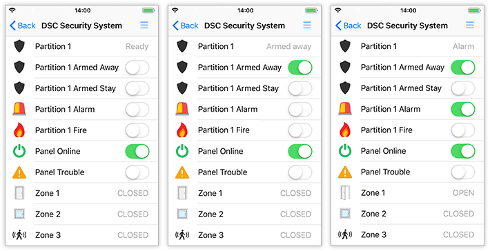
this is to capture our discussion and progress on how to properly update HomeKit SecuritySystem Service when a change happens in the Alarm system (accessory to Homekit)
To prove and discover how it is supposed to work, I coded a simple HAP-Node script, that adds the SS service/acc and listens on MQTT for commands.
In order to get HomeKit SS icon to go from OFF to Arming then to Home, the sketches in this library have to send over to MQTT:
Solution 1: The "exit in progress" (not done) and then "SA" (done) as they happen on the Security Panel to mqttPartitionTopic. (In the included short video, I simulated this library sketches by sending EX for Exit delay in progress and SA for STAY ARM using mosquitto_pub.)
THEN the corresponding HomeKit script (HAP-Node, HomeBridge, MQTTThing, ...) has to handle the exit and different arming types by updating the respective SecuritySystem service characteristics [SecuritySystemCurrentState, SecuritySystemTargetState] (Issue #126 )
Solution 2 OR this library sketch publishes SA to two different MQTT topics getTargetState then to getCurrentState, first one corresponding to exit delay in progress, the second to indicate system is armed. The HomeKit script then updates the appropriate characteristics.
Depending on the chosen solution, the https://github.com/taligentx/dscKeybusInterface/blob/master/examples/esp8266/Homebridge-MQTT/Homebridge-MQTT.ino needs to send some payload to indicate there is an exit in progress. Or publish SA to those two homekit topics...
I made your project (VirtualKeypad-Blynk.ino), it is very useful and powerful. I use your ESP8266 blynk example, I havent modified it. The ESP sends data to my Blynk server which is on my local area network, working on an Orange PI Zero. I have also made your pcb with a 2n2222 transistor. Everything working fine for few days, 2 or 3 days. After the ESP freezes and need to hard reset. After reset it, working again. I have made some investigation, I have added a terminal and do some printing. It say "Keybus buffer overflow". I increased the dscBufferSize in the library: src/dscKeybusInterface.h. Now I havent got buffer overflow, but it freezes as before. Does anybody have the same problem? Or yours working for months or years? I have 5v swithing regulator like this:
https://www.banggood.com/3A-UBEC-Module-Low-Ripple-Bluesky-Mini-Switch-Mode-DC-BEC-5V-12V-2-6S-Supply-p-993056.html?rmmds=search
, and I am powering the ESP on the Vin pin with 5V.
Please help me!
Fire Alarm (Zone 10) not reported in status sketch.
Zone open: 10  // Fire alarm zone activated
Zone open: 2
Zone open: 1
...
...
Zone restored: 2
Zone restored: 10 // Fire alarm zone restored
Log_PowerSerie832_PC5015-FIRE_ALARM_zone10_Status.txt
Log_PowerSerie832_PC5015-FIRE_ALARM_zone10_KeybusReader.txt
the F A P buttons of the pc585 and pc1565 keypad do not send any data to the serial port when pressed for 3 seconds
in the pc1832 panel works perfectly
Hi, i do not quite understand how the virtual keypad keys works ... So the code set in the virtual keyboard will put the panel under guard?
Sorry for my english, i'm using an translator
If you've tested the develop branch, feedback would be useful prior to merging with master. Thanks!
Hi,
Sorry to open an issue just for a question buy I didn´t know how to contact you.
In regards of wiring... I want to arm the alarm with Home Asisstant. Do I need to make the connection with the transistor as indicated for Virtual keypad or not?
In case I need it: I see that the normal connection and the Virtual Keypad connection both uses the same green DSC wire. To use the Virtual Keypad should I replace the 10k resistor wiring with the 1k+transistor connection or should I connect both things to the same wire (leaving both connections at the same time)
Thanks in advance for your answer.
Best regards.
WAIT - I WILL INSTEAD TRY TO HAVE MY OWN INIT IN THE BEGINING OF THE LOOP, IT MAY BE BETTER IF THIS IS CONTROLLED BY RESPECTIVELY IMPLEMENTATION
Provide an init value for at least Fire and Alarm at startup, meaning let the Change flag be true once.
The logic as of today provides updates only if there has been a status change. In the Homey app there is an absence of the status in the Fire and Tamper alarm device since nothing is provided. The status change for these are quite rare!
It may be needed to have a minor delay, or trigg on another status change in order to ensure listening systems such Homey is established.
// Publish alarm status to Homey
    if (dsc.partitionAlarmChanged) {
      dsc.partitionAlarmChanged = false;  // Resets the partition alarm status flag
      if (dsc.partitionAlarm) Homey.setCapabilityValue("alarm_tamper", true);
      else Homey.setCapabilityValue("alarm_tamper", false);
    }
Hi, do we have any possibility to read values from display.
One issue I am facing - 2x per year we are shifting from Summer to Winter time and vice verse. (Plus my clock is not accurate) I would be happy to get an access to current data/time setting and if they are shitted, then push an update to correct one
Hi,
Serial output
DSC Keybus Interface is online.
3.00: [0x00] Unrecognized data[CRC OK]
all connect properly (i think) using bc547b (cross collector and emiter in ori schematic diagram) this same problem when use sketch VirtualBlynk. In serial see only DSC Keybus Interface is online or nothing. Connected with server, blynk aplication connected to server properly but nothing works when zone is open or using keyboard. Whats going on? I mistake something? I using esp 12E not nodemcu (waiting for delivery).
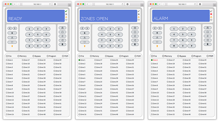
QR code with 64 zones didn`t working i send you PM about problem. Hope you understand.
P.S. I use PC5020 + extended zone module pc5108 ( 4 pcs conected at this moment, but have 7 or 8 pcs ) 2 x LCD keyboard and PGM 5208?
P.S 2 Today i did next module for esp8266 with bc547b all pinouts is ok, on diffrent keybus reader sketch from dj slow library in arduino works ok. I think the problem is on sketch or esp. Any ideas?
P.S. 3
No WAI! i read the sketch again and see the problem. Problem is pin configuration, i have naked esp8266 12e and change the pin configuration
#define dscClockPin 5 ( change from D1) // esp8266: D1, D2, D8 (GPIO 5, 4, 15)
#define dscReadPin 4 (change from D2) // esp8266: D1, D2, D8 (GPIO 5, 4, 15)
#define dscWritePin 15 (change from D8) // esp8266: D1, D2, D8 (GPIO 5, 4, 15)
Now it works with some problems, in 32 zones there is a little buggy for me (can`t report zone 17-32 and up like this issue #31) - only info on lcd "zones open" but no light buttons , 1-16 work ok, I need 64 zones for my alarm. Qr code in sketch for 64 zones is faulty. Please update link or clone and share good blynk with 64 zones. In blynk can i use 2 buttons next or prev?
A declarative, efficient, and flexible JavaScript library for building user interfaces.
🖖 Vue.js is a progressive, incrementally-adoptable JavaScript framework for building UI on the web.
TypeScript is a superset of JavaScript that compiles to clean JavaScript output.
An Open Source Machine Learning Framework for Everyone
The Web framework for perfectionists with deadlines.
A PHP framework for web artisans
Bring data to life with SVG, Canvas and HTML. 📊📈🎉
JavaScript (JS) is a lightweight interpreted programming language with first-class functions.
Some thing interesting about web. New door for the world.
A server is a program made to process requests and deliver data to clients.
Machine learning is a way of modeling and interpreting data that allows a piece of software to respond intelligently.
Some thing interesting about visualization, use data art
Some thing interesting about game, make everyone happy.
We are working to build community through open source technology. NB: members must have two-factor auth.
Open source projects and samples from Microsoft.
Google ❤️ Open Source for everyone.
Alibaba Open Source for everyone
Data-Driven Documents codes.
China tencent open source team.