Code Monkey home page Code Monkey logo

slicerbonereconstructionplanner's Introduction

BoneReconstructionPlanner

License

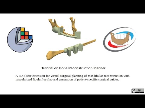
A 3D Slicer extension for virtual surgical planning of mandibular reconstruction with vascularized fibula free flap and generation of patient-specific surgical guides.

Virtual Surgery Planning Patient-specific Surgical Guides
Custom Fibula Guide Use (link below) Neo Mandible (link below)
GRAPHIC EXPLICIT PHOTO GRAPHIC EXPLICIT PHOTO
Pre Surgery Photo (left) and Post Surgery Photo (right) [*]
Pre Surgery Orthopantomogram [*] Post Surgery Orthopantomogram [*]
[*]: marked pictures belong to the same surgery and patient

Citations

If you use BoneReconstructionPlanner please cite our paper: https://www.sciencedirect.com/science/article/pii/S2666964123000103

@article{MAISI2023100109,
   title = {In-house virtual surgical planning for mandibular reconstruction with fibula free flap: Case series and literature review},
   author = {Steve Maisi and Mauro Dominguez and Peta Charmaine Gilong and Chung Tze Kiong and Syarfa Hajam and Ahmad Fadhli Ahmad Badruddin and Han Fong Siew and Saravanan Gopalan and Kok Tuck Choon},
   journal = {Annals of 3D Printed Medicine},
   volume = {10},
   pages = {100109},
   year = {2023},
   issn = {2666-9641},
   doi = {https://doi.org/10.1016/j.stlm.2023.100109},
   url = {https://www.sciencedirect.com/science/article/pii/S2666964123000103},
   keywords = {Virtual surgical planning, In-house VSP, Fibula free flap, Mandibular reconstruction},
}

Table of Contents

Description

From the engineering point of view this project attemps to be a What You See Is What You Get (WYSIWYG) editor.

Historically, this project started as Mauro I. Dominguez (EIE, FCEIA, UNR) MScEng Final Project with PhD Andras Lasso (PerkLab, Queens) supervision and Dr Manjula Herath (Malmö University) clinical advice on 2021. After first semester of '21 the project is maintained and keeps growing from Mauro's ad-honorem work.

Its math is robust so you should be able to correctly modify the reconstruction digitally at submillimeter scales (i.e. at features-sizes your eyes will not be able to distinguish).

Digital means ideal but real-world objects are not, and neither are our inputs (e.g. CT slice thickness, bone models triangle density, smoothing factor, fibula centerline, etc). In addition to that have in mind that other sources of errors (printer resolution, printing orientation, anatomic fit considerations, etc) will add up although most of the time they'll be negligible, that is assumed because complaints have not been reported.

As far as we know our BoneReconstructionPlanner custom surgical guides will be accurate and effective enough to be adequate tools. Although, you are invited to do a mock surgery to sawbones using BoneReconstructionPlanner designed instruments yourself and weight the results before attempting their use on a IRB-approved case.

Benefits:

  • less operation time
  • less ischemic time
  • less length of hospital stay after surgery
  • better osteotomies accuracy
  • better neomandible contour, more aesthetic

Cons:

  • VSP software license (free if using BoneReconstructionPlanner, 15k USD annual license if using commercial software)
  • 3D printer, biocompatible material, sterilization (can be done on an in-house 3D printing lab or outsourced)
  • needs research-review-board or FDA approval
  • half an hour preoperative plan (plenty net time is still saved)
  • learning curve for new user or need of biomedical engineer or qualified technician

User Considerations:

  • There are some parameters like the distance between faces of the closing-wedge osteotomies of fibula that can be increased if desired.
  • Deviations from the Virtual Surgical Plan could come from big slice thickness CTs, suboptimal segmentation to 3D model convertions, big extrusion layers while 3D printing the guides, not accounting for tool fitting (e.g. periosteum remainings over bone, boneSurface2guideSurface fitting, etc) and other reasons.

Interactive VSP demo

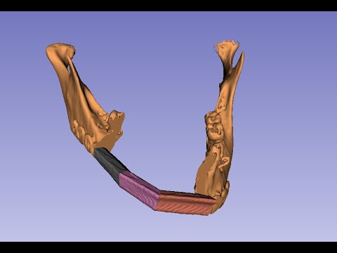
See a finished Virtual Surgical Plan of a Mandibular Reconstruction using Fibula Pieces.
Link: https://3dviewer.net/index.html#model=https://github.com/SlicerIGT/SlicerBoneReconstructionPlanner/blob/main/BoneReconstructionPlanner.gltf

Teaser and Tutorial Videos

Teaser Tutorial
https://www.youtube.com/watch?v=wsr_g_1E_pw https://www.youtube.com/watch?v=g9Vql5h6uHM

Documentation

Reported Use Cases

See the results of other users:

Sample Data

Instructions

(last validated 12/27/2023)

Installing BoneReconstructionPlanner

  1. You need Slicer 5.6.1 Stable. You have 2 options to download it:
    • Use a download link provided by Kitware: Windows, macOS, Linux
    • You can shift back the Slicer download link some number of days to an older version, for example 20 days, with https://download.slicer.org/?offset=-20 (Increase the shift until you get version 5.6.1 on the Stable release row)
  2. Install Slicer
  3. Open Slicer
  4. Press Ctrl+4 to open the extension manager. Or click the upper-right icon with the letter 'E'
  5. Go to 'Install Extensions' tab
  6. On the upper-right search box write "BoneReconstructionPlanner"
  7. Click install and give okay to install other extensions if asked (wait till ALL dependencies are installed completely).

Segmentation (Preparation for Virtual Surgical Planning)

Make a mandible segmentation and a fibula segmentation.

Example:

  1. CTs should have a recommended slice thickness of 0.65mm (or a maximum slice thickness of 1mm)
  2. Go to the segment editor. Create a new segmentation. Create a new segment, name it 'fibula'.
  3. Use threshold effect to select bone but not connecting tissue (like ligaments). Check if your selected threshold value is okay if there is no connection of the segmented bones near the joint. Threshold value should not be too low to not lose detail. Suggested value: 200
  4. Use Islands effect, select 'keep selected island' and click over the fibula to keep it.
  5. If successful continue. If not start over and use a higher threshold value or use scissors to isolate the fibula
  6. Go to Wrap Solidify effect, on Advanced button set the suggested configuration below (by @SteveMaisi) and click apply. (This is needed because it is recommended that bone segmentations have no holes inside so the assisted miterBox positioning algorithms work well) 192679644-995cbed7-9732-4f87-a936-55e000179fc4
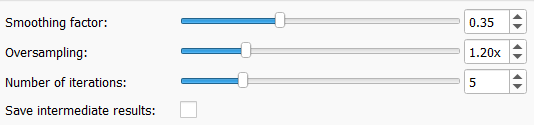
  7. Restore the segmentation smoothing factor to 0.5 4350535f4e0b0d5738701e8257e30728b26b0b96
  8. Correct errors on segmentations with scissors if needed.
  9. The bone segment (fibula or mandible) should be the first of the segment-list of the segmentation. In other words the bone segment should be in position zero of the list.

Virtual Surgical Planning

  1. Save frequently as the surgical plan can be reopened from where you left it if there is a crash (software malfunction). We are trying to fix a bug that makes Slicer close unexpectedly (more info here)
  2. Click the search icon on the left of the module selector and write 'BoneReconstructionPlanner'. Click switch to module.
  3. Select the mandibular segmentation and the fibula segmentation.
  4. Click "Create bone models from segmentations"
  5. Click "Add mandibular curve" and create a curve along the mandible. This will help giving the cut planes their initial position. It's a bit important to make it quite similar to the ideal mandible curve the patient would have if he was healthy because the plane positioning algorithms depend on it.
  6. Click "Add cut plane" and click where you want plane. Add as many planes as needed. There will be a bone piece between every two adjacent planes. So the number of mandible planes should be the desired number of bone pieces for the reconstruction plus one. The first and the last mandible planes will be the mandible resection cuts.
  7. Click "Add fibula line". Draw a line over the fibula on the 3D view. First point distal, last point proximal.
  8. Click "Center fibula line using fibula model" to make the line be similar to the anatomical axis of the fibula.
  9. Tick these options: "Automatic mandibular planes positioning for maximum bones contact area", "Make all mandible planes rotate together"
  10. Click "Update fibula planes over fibula line; update fibula bone pieces and transform them to mandible" to make the reconstruction and create the fibula cut planes.
  11. Move the mandible planes as desired to change the position/orientation of the cuts.
  12. Click "Update fibula planes over fibula line; update fibula bone pieces and transform them to mandible" again. And repeat as many times as needed. If you tick the button it will react on plane movements and update automatically.

Personalized Fibula Guide Generation

  1. Press shift over some fibula piece on the corresponding 3D view. The model should be visible on the 2D slice with the corresponding color as an edge. Create a line over the 2D slice of the fibula that will set the direction of the miterBoxes (with this you select, for example, lateral approach or posterior approach). The line should me drawn from the centerline of the fibula to a point that is distal from the first one on the 2D slice of the fibula.
  2. Select the parameters of the miter boxes: lenght, width, height, wall thickness and tolerance (this last option is inside the Settings widget and it applies also to sawBoxes of the mandible). The combination of tolerance and the slot width suggested by most experienced user (@mrtig) is:
It's easy to find out what good fit for the saw blade is by printing a few pockets with different widths. It depends on the printing technology. There is a summary at the end.

The saw blade used on this example is 0.2mm. If I print using the SLA printer I make the pockets 0.3 mm. With the FDM printer the width needs to be 0.6 mm. And the default tolerance is 0.2mm

These are the equations:

Suggested sawBoxSlotWidths
If SLA is used:
sawBoxSlotWidth = sawBladeWidth + 0.1mm
else if FDM is used:
sawBoxSlotWidth = sawBladeWidth + 0.4mm

realSawBoxWidth = sawBoxSlotWidth+2*clearanceFitPrintingTolerance

So for this example we have:
If SLA is used:
realSawBoxWidth = sawBladeWidth + 0.1mm +2*clearanceFitPrintingTolerance = 0.2mm + 0.1mm + 2*0.2mm = 0.7mm
else if FDM is used:
realSawBoxWidth = sawBladeWidth + 0.4mm +2*clearanceFitPrintingTolerance = 0.2mm + 0.4mm + 2*0.2mm = 1.0mm

From these we can find the realClearanceFitPrintingTolerance (that should be used with the realSawBoxWidth) as:
If SLA is used:
realClearanceFitPrintingTolerance = (realSawBoxWidth - sawBladeWidth)/2 = (0.7mm - 0.2mm)/2 = 0.25mm
else if FDM is used:
realClearanceFitPrintingTolerance = (realSawBoxWidth - sawBladeWidth)/2 = (1.0mm - 0.2mm)/2 = 0.4mm

As a summary:
You should use these equations
- sawBoxWidth = sawBladeWidth
- If SLA is used:
clearanceFitPrintingTolerance = 0.25mm
else if FDM is used:
clearanceFitPrintingTolerance = 0.4mm

  1. Click "Create miter boxes from fibula planes". The yellow miterBoxes will appear, each one with a long box that will create the slit for the saw to go through.

Create the Fibula Guide Base

  1. Go to the segment editor, add a new segment and create a copy (using the copy-logical-operator) of the fibula segment, rename it to "fibGuideBase".
  2. Use Hollow tool with "inside surface" option and some "shell thickness" between 3 to 6mm. The number should be decision of the user. Usually more thickness makes the contact between the miterBoxes and the guideBase easier to achieve but sometimes the guideBase ends up too big wasting material or being uncomfortable. You can solve this, using a smaller shell if you do "masked painting" in the areas that need filling. Here is explained how to do it
  3. Go to the data module and leave only the fibGuideBase segment visible on its segmentation, right-click it and press "Export visible segments to models"

Finish the Fibula Surgical Guide

  1. On the "Fibula Surgical Guide Generation" layout of BRP click on the button "Create fiducial list" and position around one point per segment were you want the screw-hole to be (the fibGuideBase model should be visible).
  2. Select the fibula guide base model that you exported on the corresponding model selector. Be sure the correct pointList is selected on the corresponding point selector. If you go by defaults it should work fine.
  3. Click "Create cylinder from fiducial list and fibula surgical guide base". Some cylinders should appear over the fibula guide base.
  4. Congratulations: You are ready to execute boolean operations to create the guide. Click on "Make boolean operations to surgical guide base with screwHolesCylinders and miterBoxes". The guide will be created, you can be sure by using the NodeControlBox that is above and hiding everything else by clicking each "eye icon" of the component objects. The name of the guide will end with the word "Prototype". If you execute this button again after you did some changes to the plan (e.g. changed miterBoxes position) a new prototype will be created.

Personalized Mandible Surgical Guide

The workflow doesn't differ much from fibula guide creation. Except that:

  • The sawBoxes are movable and you should only move them inside the cut plane, to correct automatic mispositioning. After that hide the "biggerSawBoxes interaction handles" so you have a comfortable experience on later steps.
  • You need to segment two guide bases, one for each planar cut, and copy them together to the same segment. Then export them as a unique model as explained on the earlier section.
  • You may like to create a bridge between both mandibleGuides to make a rigid connection between them. This is done with the module "MarkupsToModel" and it's very easy to use.
  • You need to put the correct models on the corresponding selectors on "Mandible Surgical Guide Generation" panel

Mandible Reconstruction Simulation

  1. Do a Virtual Surgical Plan
  2. Click "Create 3D model of the reconstruction for 3D printing". This button maybe useful for users that want to prebent plates.

User contributions and feedback

Fell free to open an issue (yes, you need a Github account) if you find the instructions or the videotutorial inaccurate, or if you need help finishing the workflow

License

slicerbonereconstructionplanner's People

Contributors

cmfsx avatar jamesobutler avatar lassoan avatar mauigna06 avatar

Stargazers

 avatar  avatar  avatar  avatar  avatar  avatar  avatar  avatar  avatar  avatar  avatar  avatar  avatar  avatar  avatar  avatar  avatar  avatar  avatar  avatar  avatar  avatar  avatar

Watchers

 avatar  avatar  avatar  avatar  avatar  avatar  avatar  avatar  avatar

slicerbonereconstructionplanner's Issues

Cutting guide boxes extruded out from fitting surface of fibula cutting guide

Hello. I'm having trouble with my fibula cutting guide because the cutting boxes are extruded from the guide's fitting surface (orange arrows). I've experienced this issue twice in past cases, and it's coming up again. It's not too bad because I can still trim it off after it's printed. Is there a way to fix this?

image

Next things to work on

Next things to work on:

  1. Make fibula bone segments with Dynamic Modeler and transform them back to the mandible
  2. Set up color for planes
  3. Place planes with one click over MandibleCurve
  4. Automatic segments distancing

biggerMiterBox transform problem

mandibleCurve has a crescent direction from the starting point to the endPoint.
If mandiblePlanes are created in decrescent order the biggerMiterBoxes won't transform well (like in the picture)

Screenshot7

Workaround till the bug is fixed: create the mandible planes in crecent order.

Follow the picture.

Captura2

Mandibular Plane

I would prefer by default to have the interaction handles to appear (with a glyph size of around 2.5%) when the plane is created as it will need to be adjusted by the surgeon on the mandible.

Tutorial of Dental Implants Planning Feature

dentalImplantsPlanningOnBoneReconstructionPlanner

  1. To plan dental implants first create a fiducial list with dental implants initial positions clicking "Create fiducial list".
  2. Then select desired (dental implant) cylinder radius, cylinder height and drill guide wall width.
  3. After that click "Create cylinders from fiducial list and mandible reconstruction".
  4. Translate and rotate the implant cylinders to the desired position and orientation using the interaction handles.
  5. Click on "Update fibula dental implant cylinders" to see the position of the drill guide (biggerFibulaImplantCylinder).
    If the drill guide is outside the fibulaSurgicalGuideBase, check "Make all mandible planes rotate together" and rotate a mandible plane the same amount you would rotate the drill guide around the fibula anatomical axis to make it be above the fibulaSurgicalGuideBase. Click on "Update fibula planes...". Click on "Update fibula dental implant cylinders" and repeat this step if needed.
  6. If the biggerFibulaImplantCylinder touchs the fibula move the implantCylinder with the interaction handles a little on the Z axis (or superior) direction and click on "Update fibula dental implant cylinders".
  7. Create the miterBoxes again when you have finished with above
  8. After the drill guides and the miterBoxes are positioned correctly click "Make boolean operations..."

@cmfsx @mrtig please try this and give suggestions to improve the GUI


I'll add an option to add the boolean difference of the fibula at the end of the fibulaSurgicalGuide creation soon so you can set a "Bigger miterBox distance to fibula" equal to zero.

PS: "Select implant cylinder" selector doesn't work yet. The idea would be to only show the interaction handles of the selected implant to avoid crowding the GUI. Please recommend buttons or things you would like

Remove non-manifold edges before Boolean mesh operation

vtkbool fails (returns empty mesh or meshes with errors) for some Boolean mesh operations. We work together with vtkbool developer to identify and fix the issues.

It seems that vtkbool expects input meshes to not have any non-manifold edges (which is completely reasonable). We need to test if we detect non-manifold edges using vtkCleanPolyData and vtkFeatureEdges and then maybe stitch the holes using vtkFillHolesFilter solves the problem - see zippy84/vtkbool#40 (comment).

Fibula Segment Length

@mauigna06
While planning the video,I remember that we have not implemented a basic feature. That is the length of each fibula segment. This is one of the most important parameters for clinicians to avoid short segments and properly place the osteotomy cuts.

Is it possible to display the fibula segment lengths with hide/unhide option ( to prevent cluttering of the 3D view) ? or as a separate table ?

Display the original transparent mandible

Using the mandible-surgical-guide-feature branch. I like to display the original transparent mandible so I can better align the fibula fragments. Every time I press the update button the original model is hidden.
It would be nice if the model's visibility didn't change. Also it might be a good idea to add some user interface element so the user can quickly hide or make the original mandibula visible.

Automatic mandible reconstruction planning

I was somewhat able to reproduce the results here:
https://pubmed.ncbi.nlm.nih.gov/31886903/

I made an algorithm to decimate the mandible curve with a minimum segment length constraint, mine computes all possible decimated curves and with a metric selects the optimal one, theirs uses a modified version of Ramer-Douglas-Peucker algorithm with a minimum segment length constraint (I searched before creating mine and I didn't find the constrained version of the algorithm anywhere), I think their algorithm could end up on a localMinimum of the optimized curve. So I think mine is more exact although it takes more to compute (e.g. 9 seconds for starting number of points of the polyline equal 71 and 4 segments approximation objetive). However I could make a commandLineModule to calculate this on C++ and call it from python.

Maybe with a little bit some more work all this is publishable.

Now I just need to integrate the automatic planning function to BRP with the results of the decimated curve.

I think these are great news. What do you think @cmfsx, @lassoan, @mrtig ?

Here is an example of the result for 4 line segments approximation:
decimatedCurve0

decimatedCurve1

Meeting

Hi Andras and Manjula. Would you like to have our meeting next Tuesday at 4pm (Buenos Aires time)?

load a saved scene without bugs

Currently when you load a scene (.mrb) the mandiblePlaneObservers don't work and the input of the dynamicModelerNodes are lost. Maybe a button or an event can be used to correct these problems when a scene is loaded

Reconstructed-mandible vessel position

I saw sometimes users have a model of the fibula vessel.

vesselOfFibula

So I suppose it is important on planning to see it's relative position/orientation regarding the fibula.

I could show the vessel parts that correspond to the reconstructed fibula pieces in the position/orientation they would be if the fibulaPlanes cutted the whole leg to make the reconstruction (relative position/orientation of the vessel pieces regarding the fibula pieces is conserved).

Would this be useful? @cmfsx, @mrtig

New algorithm for curved extrusion to design the custom titanium plate

Hi. I would like you to see the results of this new algorithm dedicated to making the mesh for the base of the custom titanium plate compatible with dental implants. Here is an example scene: https://gofile.io/d/7alZoU

You can load your sample mandible CT to see how well it fits the reconstruction.
This is a prototype version and it can be improved. For example, the extrusion is not always normal to the mandible reconstruction (because it only depends on the GetCurvePointToWorldTransformAtPointIndex of the curve). In the example it works well but to guarantee that the algorithm works every time another user input would be needed.

I would like to know your opinions about how good it looks from the clinical point of view (@cmfsx) and the engineering point of view (@lassoan).
Andras, I tried to smooth it using the surfaceToolbox but I was unsuccessful. Does the mesh need to be subdivided first? I tried that and it worked kind of better but the mesh smoothed heterogeneously, no good-enough results.

The algorithm needs as input a polygon to be extruded defined in code (it's name is startingPolygonPoints) and it needs a a curve called "MarkupsCurve" to extrude along created by the user

Here is the code to execute on the python console if you want to try it:

import numpy as np

originalCurve = getNode('MarkupsCurve')

myCurve = slicer.mrmlScene.CreateNodeByClass("vtkMRMLMarkupsCurveNode")
myCurve.SetName("C2")
slicer.mrmlScene.AddNode(myCurve)
slicer.modules.markups.logic().AddNewDisplayNodeForMarkupsNode(myCurve)

points = vtk.vtkPoints()
curvePointsArray = slicer.util.arrayFromMarkupsControlPoints(originalCurve)
vtkPointsData = vtk.util.numpy_support.numpy_to_vtk(curvePointsArray, deep=1)
points.SetNumberOfPoints(len(curvePointsArray))
points.SetData(vtkPointsData)
myCurve.SetControlPointPositionsWorld(points)

myCurve.ResampleCurveWorld(10)

displayNode = myCurve.GetDisplayNode()
displayNode.UseGlyphScaleOff()
displayNode.SetGlyphSize(1.5)
displayNode.SetCurveLineSizeMode(1)
displayNode.SetLineDiameter(0.5)

xLength = 2.5
yLength = 7

startingPolygonPoints = np.array(
            [
                [xLength/2, yLength/2, 0],
                [-xLength/2, yLength/2, 0],
                [-xLength/2, -yLength/2, 0],
                [xLength/2, -yLength/2, 0]
            ]
        )

cell_array = vtk.vtkCellArray()
points = vtk.vtkPoints()
point_id = 0

startIndex = 0
curveMatrix = vtk.vtkMatrix4x4()
myCurve.GetCurvePointToWorldTransformAtPointIndex(startIndex,curveMatrix)
myCurveX = np.array([curveMatrix.GetElement(0,0),curveMatrix.GetElement(1,0),curveMatrix.GetElement(2,0)])

curveToWorldTransform = vtk.vtkTransform()
curveToWorldTransform.PostMultiply()
curveToWorldTransform.Concatenate(curveMatrix)
curveToWorldTransform.Translate(-myCurveX*xLength/2)

firstTransformedPolygonPoints = []
for i in range(len(startingPolygonPoints)):
  transformedPolygonPoint = np.zeros(3)
  curveToWorldTransform.TransformPoint(startingPolygonPoints[i], transformedPolygonPoint)
  firstTransformedPolygonPoints.append(transformedPolygonPoint)

polygon = vtk.vtkPolygon()
polygon.GetPointIds().SetNumberOfIds(4)
for i in range(4):
    points.InsertNextPoint(firstTransformedPolygonPoints[i])
    polygon.GetPointIds().SetId(i, point_id)
    point_id += 1

cell_array.InsertNextCell(polygon)

curvePoints = slicer.util.arrayFromMarkupsCurvePoints(myCurve)

for j in range(1,len(curvePoints)):
  curvePoint = curvePoints[j]
  #
  secondTransformedPolygonPoints = []
  #
  closestCurvePoint = [0,0,0]
  closestCurvePointIndex = myCurve.GetClosestPointPositionAlongCurveWorld(curvePoint,closestCurvePoint)
  #
  curveMatrix = vtk.vtkMatrix4x4()
  myCurve.GetCurvePointToWorldTransformAtPointIndex(closestCurvePointIndex,curveMatrix)
  myCurveX = np.array([curveMatrix.GetElement(0,0),curveMatrix.GetElement(1,0),curveMatrix.GetElement(2,0)])
  #
  curveToWorldTransform = vtk.vtkTransform()
  curveToWorldTransform.PostMultiply()
  curveToWorldTransform.Concatenate(curveMatrix)
  curveToWorldTransform.Translate(-myCurveX*xLength/2)
  #
  for i in range(len(startingPolygonPoints)):
    transformedPolygonPoint = np.zeros(3)
    curveToWorldTransform.TransformPoint(startingPolygonPoints[i], transformedPolygonPoint)
    secondTransformedPolygonPoints.append(transformedPolygonPoint)
  
  for i in range(4):
    points.InsertNextPoint(secondTransformedPolygonPoints[i])
    point_id += 1
  
  for k in range(len(firstTransformedPolygonPoints)):
    polygon = vtk.vtkPolygon()
    polygon.GetPointIds().SetNumberOfIds(3)
    polygon.GetPointIds().SetId(0, k + point_id - len(secondTransformedPolygonPoints))
    polygon.GetPointIds().SetId(2, k + point_id - 2*len(secondTransformedPolygonPoints))
    if k!=3:
      polygon.GetPointIds().SetId(1, k + 1 + point_id - len(secondTransformedPolygonPoints))
    else:
      polygon.GetPointIds().SetId(1, point_id - len(secondTransformedPolygonPoints))
    
    cell_array.InsertNextCell(polygon)
    #
    polygon = vtk.vtkPolygon()
    polygon.GetPointIds().SetNumberOfIds(3)
    polygon.GetPointIds().SetId(0, k + point_id - 2*len(secondTransformedPolygonPoints))
    if k!=3:
      polygon.GetPointIds().SetId(1, k + 1 + point_id - len(secondTransformedPolygonPoints))
      polygon.GetPointIds().SetId(2, k + 1 + point_id - 2*len(secondTransformedPolygonPoints))
    else:
      polygon.GetPointIds().SetId(1, point_id - len(secondTransformedPolygonPoints))
      polygon.GetPointIds().SetId(2, point_id - 2*len(secondTransformedPolygonPoints))
    
    cell_array.InsertNextCell(polygon)
  
  firstTransformedPolygonPoints = secondTransformedPolygonPoints.copy()
  #
  if j == len(curvePoints)-1:
    polygon = vtk.vtkPolygon()
    polygon.GetPointIds().SetNumberOfIds(4)
    for i in range(4):
        polygon.GetPointIds().SetId(i, point_id-4)
        point_id += 1
    
    cell_array.InsertNextCell(polygon)
  

polydata = vtk.vtkPolyData()
polydata.SetPoints(points)
polydata.SetPolys(cell_array)

triangleFilter = vtk.vtkTriangleFilter()
triangleFilter.SetInputData(polydata)
triangleFilter.Update()

extrusionModel = slicer.mrmlScene.CreateNodeByClass("vtkMRMLModelNode")
slicer.mrmlScene.AddNode(extrusionModel)
extrusionModel.CreateDefaultDisplayNodes()
extrusionModel.SetAndObservePolyData(triangleFilter.GetOutput())

License of the module

Even though I'm doing my best creating this module. And the code from the branches is reviewed before going to main. This is not FDA approved medical software.
Should we add a sentence to the license like "For research use only. Not clinical use"?
I would like the user to know that he takes full responsability of the results while using the module for surgery planning. Should the license be more clear about this or it is enough with the current text?

SlicerRT is now a dependency of this module

An SlicerRT filter, vtkCollisionDetectionFilter, is used to check the security margin between fibula pieces. You can also disable "Check security margin on miter box creation" and you will not need this dependency.
vtkCollisionDetectionFilter is available in preview releases of Slicer but I think our focus should be to give support to the stable release.

Other dependencies are:
Sandbox: CombineModels module used to make boolean operations between meshes to make the surgicalGuides
MarkupsToModel: used to create the mandibleBridge for mandibleSurgicalGuides
SurfaceWrapSolidify: Used to eliminate holes from bone segments. Needed for sawBoxes/miterBoxes positioning algorithm to work well.

I'll add this information to the readme shortly

Combine Models module not working

Steps to recreate the bug:
Load model a model in "Input model A", load another model in "Input model B", select operation "Difference (A-B)", output "Create new model node", click "Apply"

Gives the following error on the python interactor:

Traceback (most recent call last):
  File "C:/Users/Mau/Documents/GitHub/SlicerSandbox/CombineModels/CombineModels.py", line 238, in onApplyButton
    self._parameterNode.GetParameter("Operation"))
  File "C:/Users/Mau/Documents/GitHub/SlicerSandbox/CombineModels/CombineModels.py", line 292, in process
    import vtkSlicerCombineModelsModuleLogicPython as vtkbool
ModuleNotFoundError: No module named 'vtkSlicerCombineModelsModuleLogicPython'

Third surgical guide created

Hi guys, here is the scene containing the latest surgical guide made with the module. Please be sure to use the branch "booleanOperationsExperiments" to open it so you can edit the parameters and do the modifications you'd like...

https://gofile.io/d/nPaSD8

Screenshot2

(Before doing anything click on "Create bone models from segmentations" so the bone models are loaded to the logic )

Meeting

Hi @lassoan and @cmfsx . I would like to schedule a meeting to talk about how the project should follow, how the module should change to be possible to make surgical guides in it. When are you available?

vtkClipPolyData not working right

I generate an intersectionModel with the fibulaModel and a fibulaPlane with vtkCutter. Then I generate semiIntersectionModel with intersectionModel and a plane that has a normal equal to fibulaZ (the direction of the fibulaLine) and an origin equal to fibulaPlaneOrigin.
When the normal of first plane and normal of the second plane differ by very little the result of the clipping (semiIntersectionModel) is empty and has no points. How to correct this?
Here is an scene showing the problem in "semiIntersection0_A" and "semiIntersection0_B"
It appears that vtkClipPolyData is not sensitive enough.

Here is the function to create semiIntersections:

def getIntersectionBetweenModelAnd1PlaneWithNormalAndOrigin(self,modelNode,normal,origin,intersectionModel):
  plane = vtk.vtkPlane()
  plane.SetOrigin(origin)
  plane.SetNormal(normal)

  clipper = vtk.vtkClipPolyData()
  clipper.SetInputData(modelNode.GetPolyData())
  clipper.SetClipFunction(plane)
  clipper.Update()

  intersectionModel.SetAndObservePolyData(clipper.GetOutput())

#call
semiIntersectionModel = slicer.mrmlScene.AddNewNodeByClass('vtkMRMLModelNode','semiIntersection'
semiIntersectionModel.CreateDefaultDisplayNodes()
getIntersectionBetweenModelAnd1PlaneWithNormalAndOrigin(intersectionModel,fibulaZ,fibulaPlaneOrigin,semiIntersectionModel)

vtkbool not working well for intersection operations

Hi @lassoan. Would you want me to talk with the developer of vtkbool?

I'm using fibulaBonePieces intersection to detect if a cut overlaps with the adjacent bone segment, cutting it. This is useful to detect when automatic fibula bone segments distancing works wrong or if the distance is too smal. The intersections of these fibulaBonePieces should have a non-empty result and that doesn't happen.

"Fibula Segment 0A-0B.vtk" intersection "Fibula Segment 1A-1B.vtk". The result is an empty model, it shouldn't be that way.
"Fibula Segment 1A-1B.vtk" intersection "Fibula Segment 2A-2B.vtk". The result is an empty model, it shouldn't be that way.

These are the files that give problems (I've checked and they do not have any non-manifold edges)
Meshes.zip

Osteotomy(Cutting) Planes

There are two kinds of osteotomy planes for the mandible. There is no standard or conventional names to name them but for explanation I would name them as following.

  1. Mandibular resection planes
    This will always be two planes. always the first and the last plane.

1

  1. Fibula segment planes

This will be marked as one plane by the surgeon (this if possible should be taken by the point of the curve markup) and the software will need to calculate the second plane based on that so that the fibula can be physically shaped.

Depending on the number of "bone segments" needed for the reconstruction the number can vary.

In the simplest reconstruction with just one "bone segment", this plane would not be necessary.

Then if two "bone segments" are needed then one of these planes like ilustrated. then with each additioanle "bone segment (n)" this will increase (n-1) number of fibula segments will be need.

Here we will need in addition to the plane marked by the surgeon (P3), P4 and another P5 plane would be needed on the Fibula.

2

Problems with straightening transform of Curved Planar Reformat module

Hi @lassoan.

Without custom plates to ensure non-intersecting holes (of fixing screws and dental implants) in the mandible reconstruction the fibula dental implant drill guides are not so useful because eyeballing of the surgeon becomes necessary. So getting to make custom plates is very important. That way will reach to get the standard of care with BoneReconstructionPlanner.

I'm testing the principle to create the custom plate. I tried to make create the straightening transform of the curved plate using a spline curve (that resambles a linear curve for more precision because the mandible reconstruction is made of linear bone segments and the spline curve will resemble a linear curve when we use it to create a custom plate with this method).

Screenshot

Screenshot2

As you can see I couldn't achieve straightening without deformation of the mesh. There are big deformations (as in the picture) and small deformations (also slightly visible in the picture) that alter the width of the plate making it non-uniform.
I tried with smaller slice size and bigger curve resolution without better results. I don't see folding in the earlier pictures but there are abrupt changes of direction on the grid lines that I assume could have something to do with the bad results.

Even trying with a different curve that was smooth I couldn't achieve results as shown in the documentation:
goodResult

This was the best I got with the smooth curve and there are abrupt changes of direction on the grid lines:
Screenshot3

Do have any idea/suggestions of how to improve this results?

Possibilities of this project

Here I some ideas I have about this project.

I think this can already be done (at least the fibula surgical guides):
Captura23

If we get funding I think we could develop code for mandible reconstruction using iliac crest, mandible reconstruction using scapula and mandible reconstruction using rib.
We can also develop algorithm to create custom titanium plates to be 3D printed.

Here is a planning using iliac crest, making of surgical guides and custom titanium plate. It shows a process we could replicate:
https://www.youtube.com/watch?v=7RMermYOOYY

I think the main thing needed to achieve this is a new transform widget that could rotate that bone around a specified point with an axis of rotation parallel to the camera view and that it could (if desired) move the bone by moving the origin of the widget. Like this:

Captura24
https://youtu.be/7RMermYOOYY?t=98

I would like to develop it.

If custom titanium plates are made, immediate dental implants can be achieved:
Captura25
https://youtu.be/-usCFduxTV8?t=1039

There are some surgeons that plan implants without custom titanium plates putting the holes for them in fibula surgical guide:
https://youtu.be/3ly4qmrGGU0?t=404

Register sample data sets

To make testing easier, add registration of sample data sets into SampleData module. This allows single-click loading of testing data (fibula and mandible images for now, later we can add segmentation and curves as well). There is already an example in the module for registering custom two same data sets, they just need to updated with the correct name, link, and git hash.

Fibula surgical guide generation is not working

Fibula surgical guide generation is not working. Nothing happens when the boolean operation button in fibula surgical guide generator is pressed.

Please @cmfsx do open a new issue when you have this kind of problems, comments on commits are not searcheable.

Open the python interactor. Press enter a few times to separe the previous messages. And press the button to make the fibula surgical guide. Does an error appear? if so, post it.
If not, is the time of processing in any step 0.00 if this happens it means that vtkbool failed to make the boolean operation and returned an empty model. You can check this by searching in the data module a model called "FibulaSurgicalGuidePrototype" and hovering the mouse over it will tell you the number of points the model has, it should say zero. I have solved this problem moving the miterBoxDirectionLine a little bit, creating the miterBoxes again and pressing the button to create the fibula surgical guide should work now.

Name

Are we going to keep the name "SlicerBoneREconstructionPlanner" should we plan to change it narrowing the scope?

I will ask someone to work on a logo so can we finalize a name?

@lassoan are there any rules for the slicer extension logo?

Undo

Do you think it would be possible to implement an undo function?
When moving the planes it's possible to accidentally move them. It would be nice if it was possible to quickly revert to the last position.

Requeriment of more info about the workflow to continue the devepment

@cmfsx Can you upload an scene made with the module that has a fibula bone model and the fibula planes positioned as you would put them to plan a surgery (I think you said something related with that the intersections of the planes should be on the lateral side). I want this file to see how the sawBoxes should be transformed to place

Between Spaces

Once you enter the between space even though you change it later and update it is not reflected on the segments that's been transformed back to the mandible.

Recommend Projects

  • React photo React

    A declarative, efficient, and flexible JavaScript library for building user interfaces.

  • Vue.js photo Vue.js

    🖖 Vue.js is a progressive, incrementally-adoptable JavaScript framework for building UI on the web.

  • Typescript photo Typescript

    TypeScript is a superset of JavaScript that compiles to clean JavaScript output.

  • TensorFlow photo TensorFlow

    An Open Source Machine Learning Framework for Everyone

  • Django photo Django

    The Web framework for perfectionists with deadlines.

  • D3 photo D3

    Bring data to life with SVG, Canvas and HTML. 📊📈🎉

Recommend Topics

  • javascript

    JavaScript (JS) is a lightweight interpreted programming language with first-class functions.

  • web

    Some thing interesting about web. New door for the world.

  • server

    A server is a program made to process requests and deliver data to clients.

  • Machine learning

    Machine learning is a way of modeling and interpreting data that allows a piece of software to respond intelligently.

  • Game

    Some thing interesting about game, make everyone happy.

Recommend Org

  • Facebook photo Facebook

    We are working to build community through open source technology. NB: members must have two-factor auth.

  • Microsoft photo Microsoft

    Open source projects and samples from Microsoft.

  • Google photo Google

    Google ❤️ Open Source for everyone.

  • D3 photo D3

    Data-Driven Documents codes.