Code Monkey home page Code Monkey logo

power-boards's Introduction

Power Boards

Collection of DC/DC converters, battery chargers and power supplies.

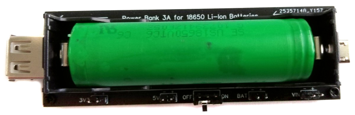
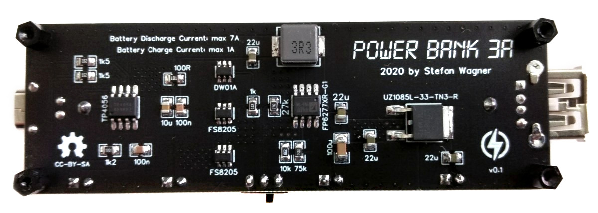
Powerbank based on FP6277 boost converter with 5V and 3.3V output up to 3A.

Power_Bank_3A_pic2.jpg Power_Bank_3A_pic3.jpg

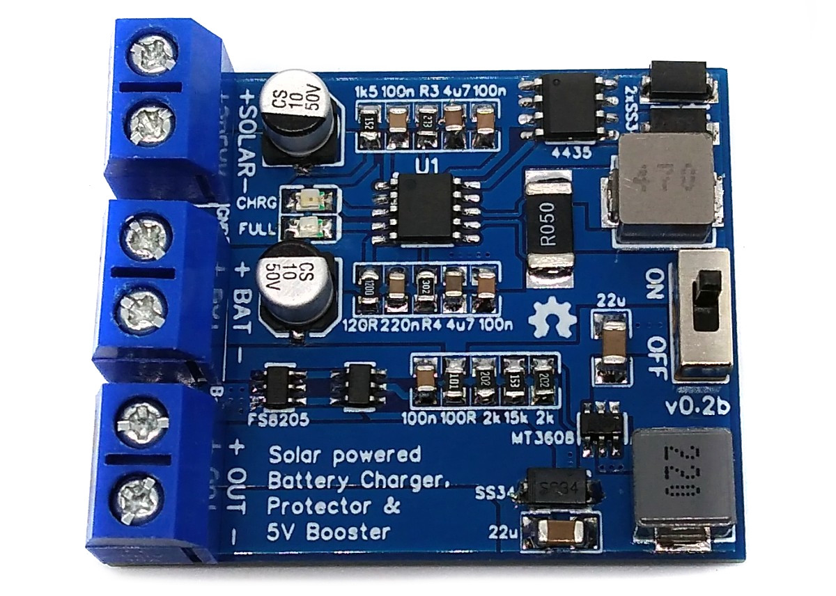
Solar powered switch-mode charger (CN3801), protector (HY2112) and 5V booster (MT3608) for LiFePO4 batteries. The charger provides maximum power point tracking (MPPT) and can easily be modified to work with LiPo batteries.

Solar_Charger.jpg

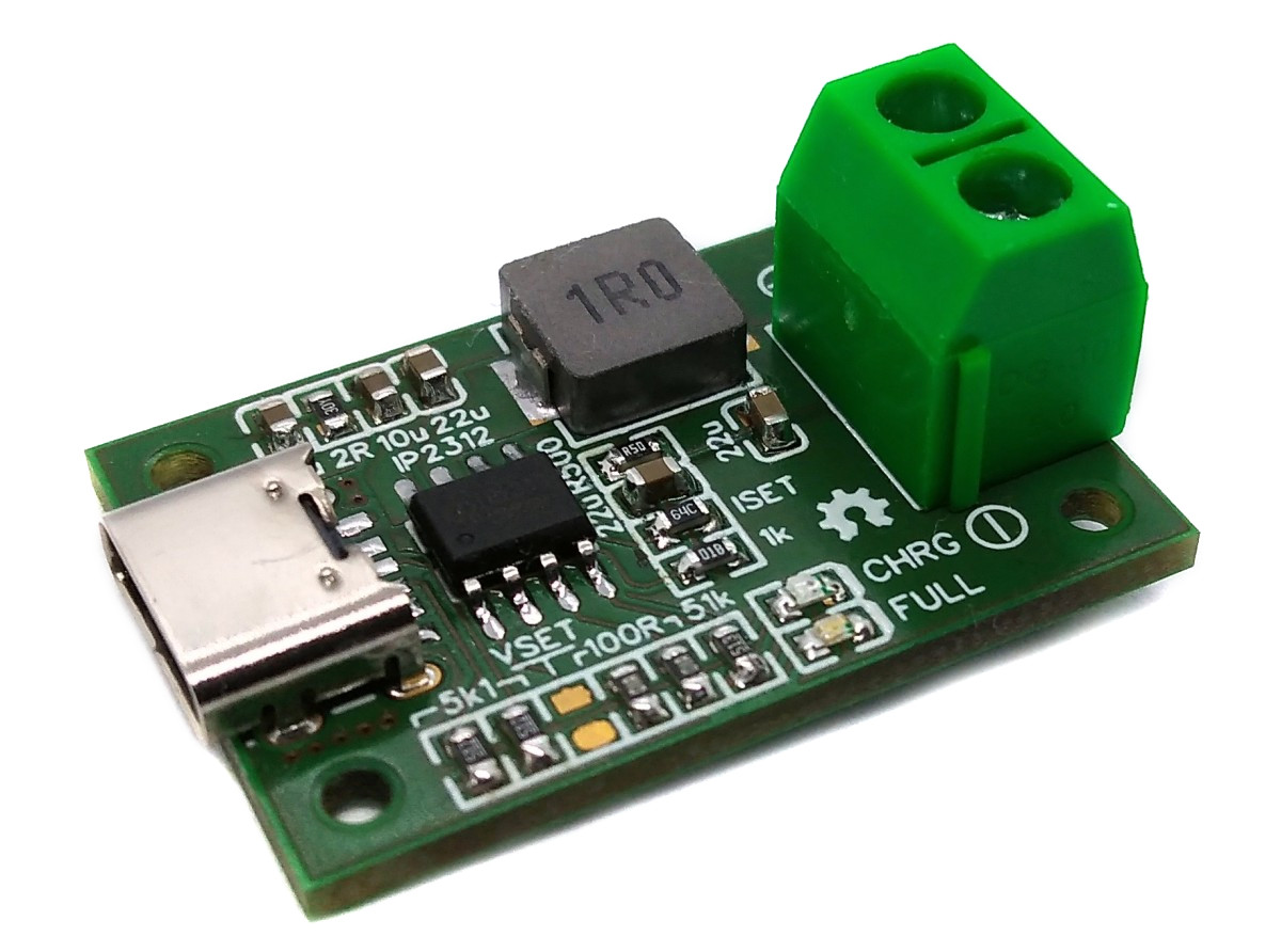
Single cell Li-Ion/LiPo battery synchronous switch-mode fast charging board (up to 3A) with USB Type-C port.

LiPo_Charger_IP2312_pic1.jpg

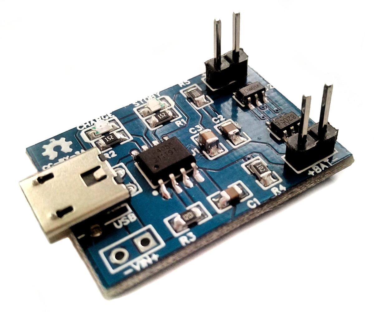
Single cell Li-Ion/LiPo battery charging and protection circuit.

LiPo_Charger_TP4056.jpg

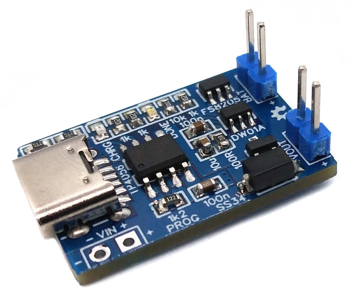
Single cell Li-Ion/LiPo battery charging and protection board with USB-C port and load sharing power path control.

LiPo_Charger_LS_TP4056.jpg

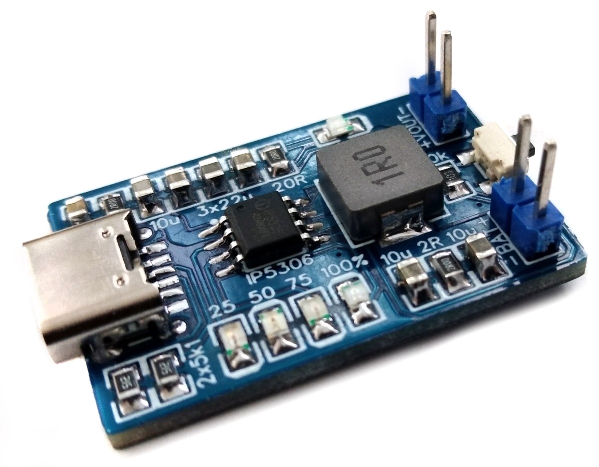
Single cell Li-Ion/LiPo battery charger, protector and 5V booster based on the IP5306 with MicroUSB or USB Type-C port.

LiPo_Power_Board_USB-C_IP5306.jpg

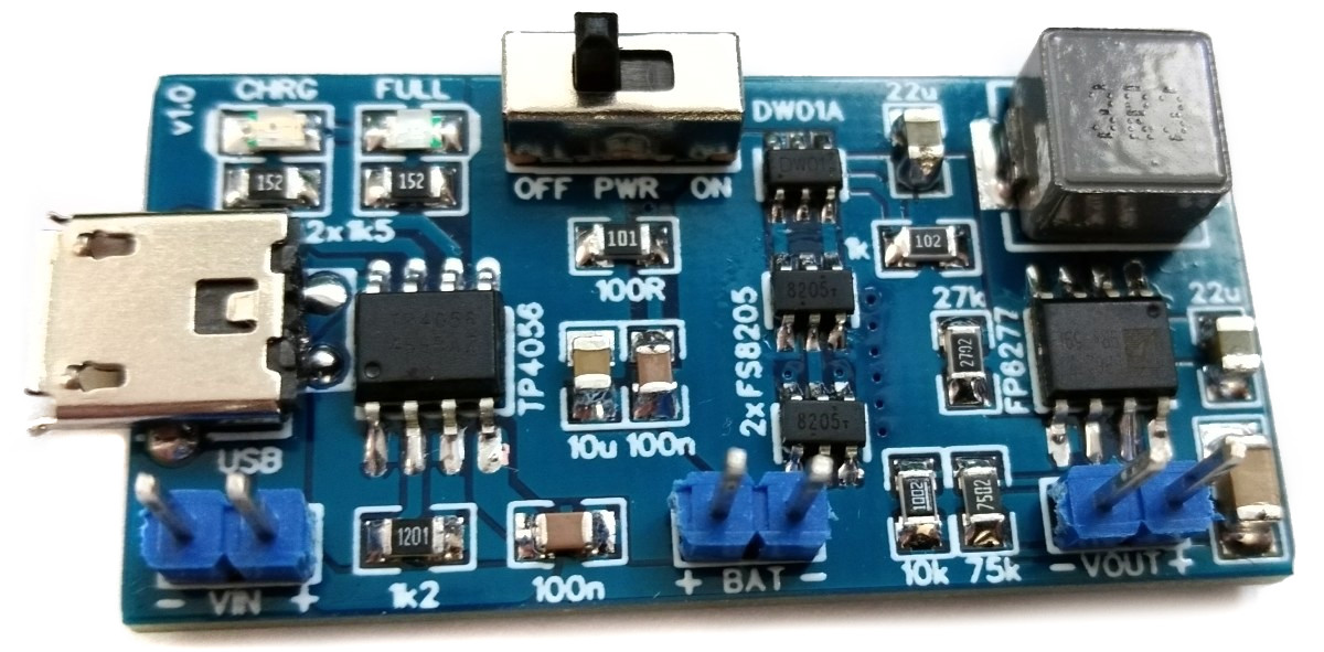
Single cell Li-Ion/LiPo battery charger (TP4056), protector (DW01A) and 5V/3A booster (FP6277).

LiPo_Power_Board_FP6277.jpg

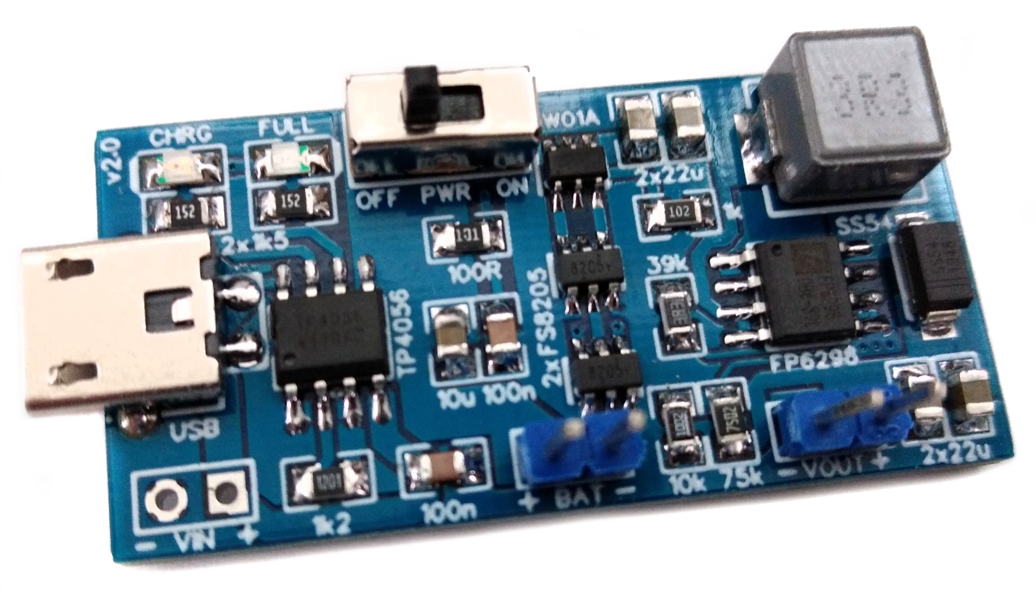
Single cell Li-Ion/LiPo battery charger (TP4056), protector (DW01A) and 5V/2A booster (FP6298).

LiPo_Power_Board_FP6298.jpg

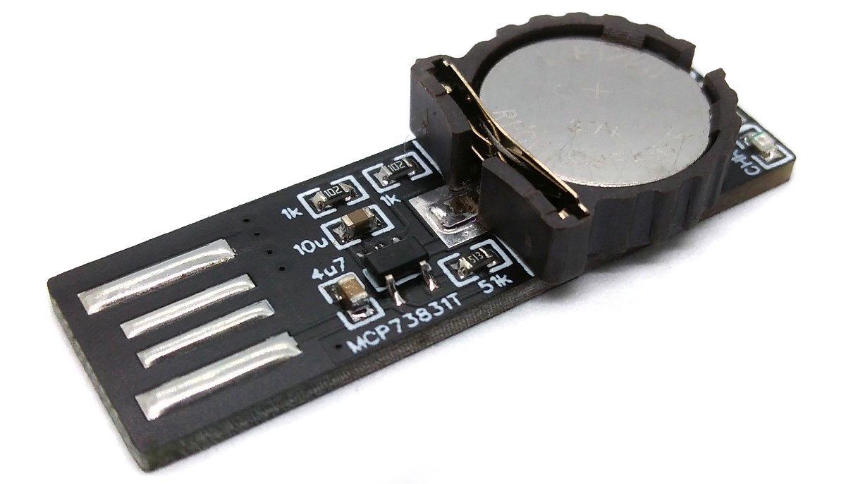
Charger for LIR1220 Li-Ion batteries.

LIR1220_Charger.jpg

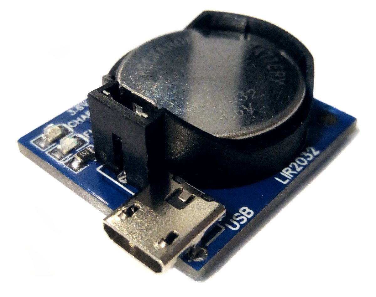
Charger for LIR2032 Li-Ion batteries.

LIR2032_Charger_TP4056.jpg

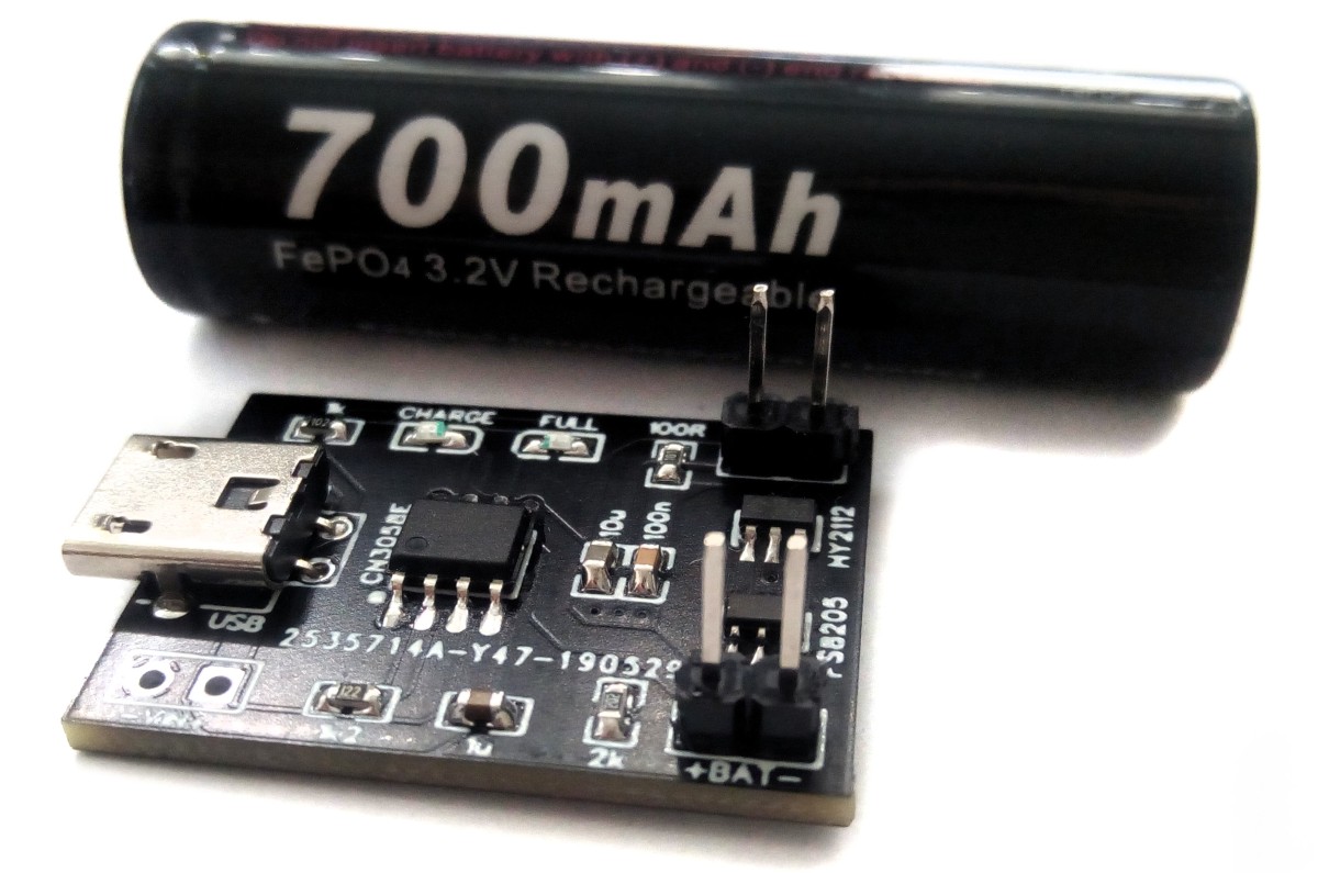
Single cell LiFePO4 battery charger and protector.

LiFePO4_Charger_CN3058.jpg

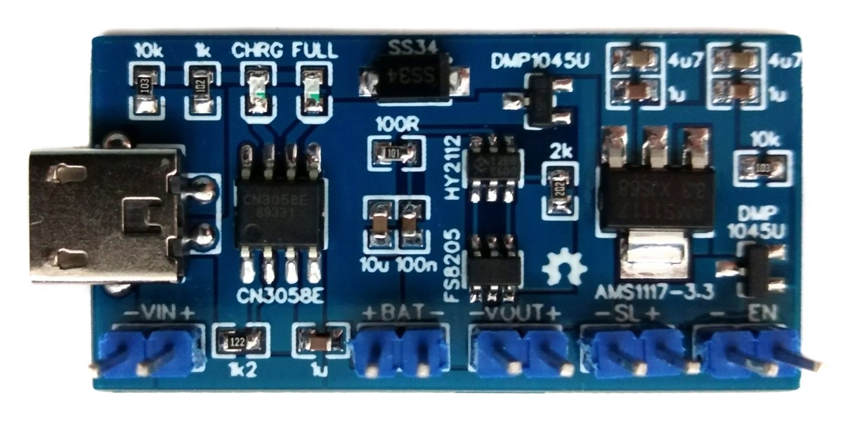
Single cell LiFePO4 charging (CN3058E) and protection (HY2112) board with load sharing power path management, 3.3V output und an additional switchable output.

LiFePO4_Power_Board_LS_3V3.jpg

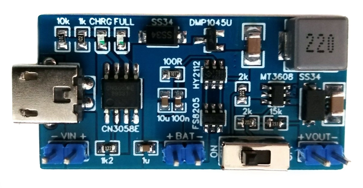
Single cell LiFePO4 charger (CN3058E), protector (HY2112) and 5V booster (MT3608) board with load sharing power path management.

LiFePO4_Power_Board_LS_5V.jpg

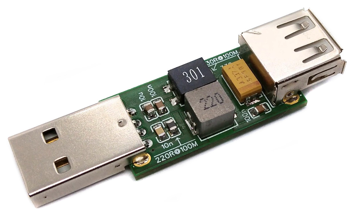
The USB Power Filter reduces noise and ripple on the 5V power rail through a combination of different low-pass filters.

USB_Power_Filter_pic1.jpg

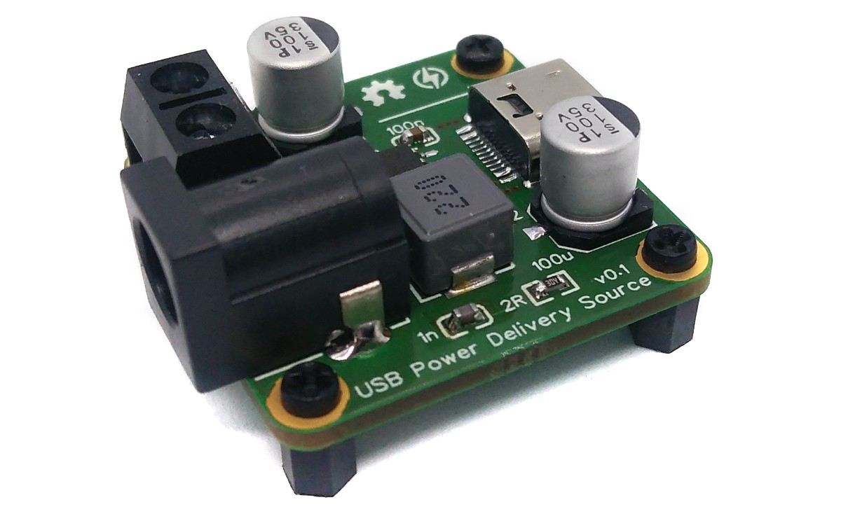
With the USB-PD Source, old power supplies can be transformed into modern fast charging adapters with a USB Type-C output port and an output power of up to 18W. The device masters the most common fast charging protocols (PD2.0, BC1.2, QC2.0, QC3.0, FCP, AFC e.g. for Apple, Samsung, Huawei) and can offer different voltages with high currents (5V/3A, 9V/2A, 12V/1.5A).

USB-PD_Source_IP6520_pic1.jpg

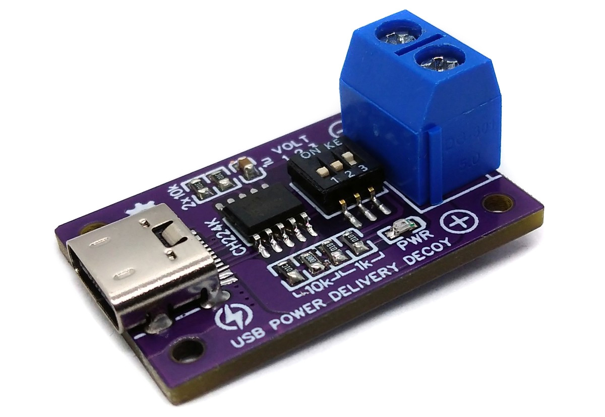
With the USB PD Decoy, a USB Type-C PD power adapter can be used as a power supply with the option of selecting different output voltages via DIP switches. It is based on the cheap and easy-to-use CH224K multi fast charging protocol power receiving chip.

USB-PD_Decoy_CH224K.jpg

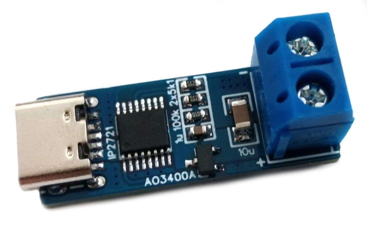
Very simple USB Type-C Power Delivery trigger board based on the IP2721 that requests the maximum voltage (up to 20V) from the power supply.

USB-PD_Max_Trigger.jpg

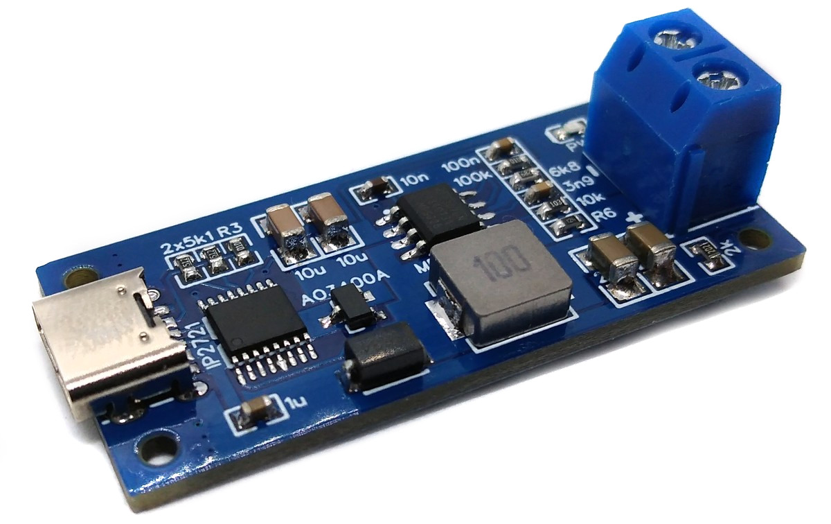
A slightly different approach to USB Type-C Power Delivery by combining a PD maximum voltage trigger (IP2721, up to 20V) and a buck converter (MP2307). The output voltage can be selected via the voltage divider (R5 + R6). The maximum output current is 3A.

USB-PD_Buck_Converter.jpg

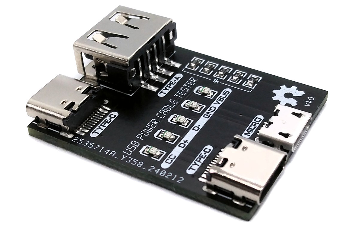
A simple testing device to verify the presence and continuity of power and data lines in USB charging cables.

USB_Power_Cable_Tester_pic2.jpg

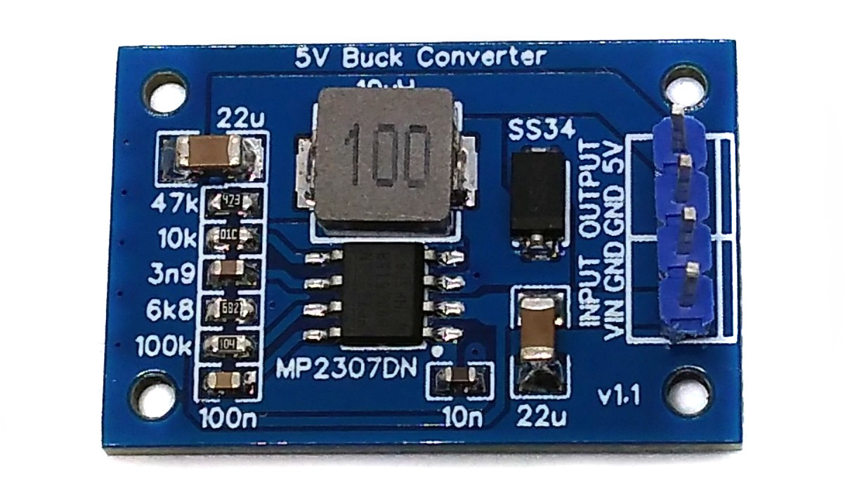
3A buck converter based on MP2307. Fixed output voltage can be defined via the voltage divider.

Buck_Converter_MP2307.jpg

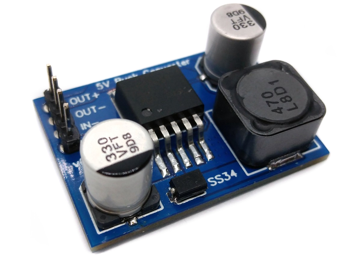
5V/4A Buck Converter based on the LM2596.

Buck_Converter_5V_LM2596.jpg

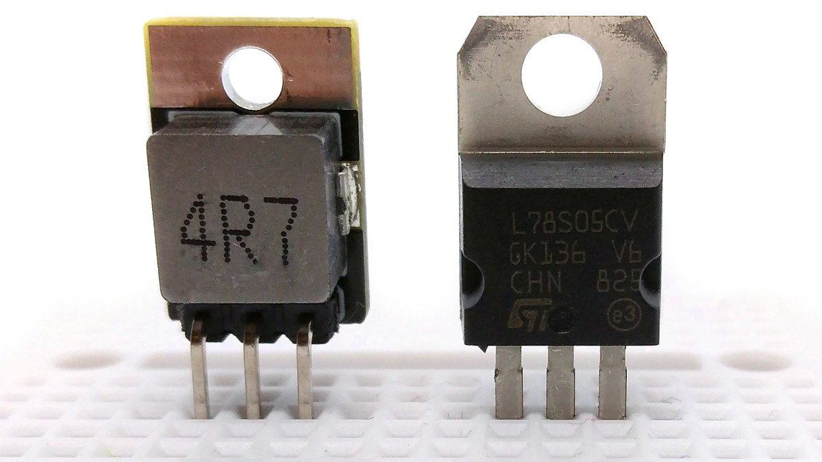
Replace your old 78xx voltage regulators with this much more efficient pin-compatible buck converter.

78xx_Replacement.jpg

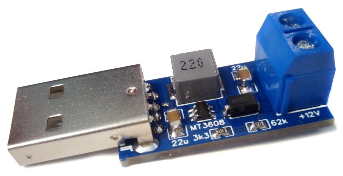
Boost converter with USB plug. Fixed output voltage can be defined via the voltage divider.

Boost_Converter_MT3608.jpg

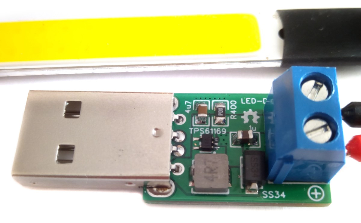
Constant current boost converter and LED Driver with USB Plug.

Boost_Converter_TPS61169.jpg

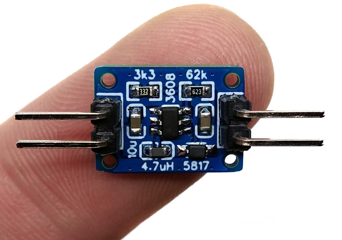
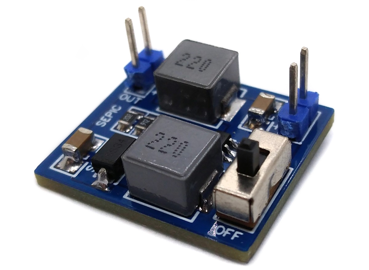
Simple SEPIC (Single Ended Primary Inductance Converter) non-inverting buck/boost converter based on the MT3608 with a fixed output voltage selectable by the resistor values of the voltage divider.

SEPIC_MT3608.jpg

Cheap and low-profile 12V boost converter based on MT3608 for low current applications (max 30mA) like high-voltage programmers.

LCBC_MT3608.jpg

power-boards's People

Contributors

wagiminator avatar

Stargazers

 avatar  avatar  avatar  avatar  avatar  avatar  avatar  avatar  avatar  avatar  avatar  avatar  avatar  avatar  avatar  avatar  avatar  avatar  avatar  avatar  avatar  avatar  avatar  avatar  avatar  avatar  avatar  avatar  avatar  avatar  avatar  avatar  avatar  avatar  avatar  avatar  avatar  avatar  avatar  avatar  avatar  avatar  avatar  avatar  avatar  avatar  avatar  avatar  avatar  avatar  avatar  avatar  avatar  avatar  avatar  avatar  avatar  avatar  avatar  avatar  avatar  avatar  avatar  avatar  avatar  avatar  avatar  avatar  avatar  avatar  avatar  avatar  avatar  avatar  avatar  avatar  avatar  avatar  avatar  avatar  avatar  avatar  avatar  avatar  avatar  avatar  avatar  avatar  avatar  avatar  avatar  avatar  avatar  avatar  avatar  avatar  avatar  avatar  avatar  avatar

Watchers

 avatar  avatar  avatar  avatar  avatar  avatar  avatar  avatar  avatar  avatar  avatar  avatar  avatar  avatar  avatar  avatar  avatar  avatar  avatar  avatar  avatar  avatar

power-boards's Issues

Suggestion for USB PD Trigger with gimmicks

It would be nice to see also a PD Trigger with a cheap MCU which allows to set a target voltage, but with
a buck and boost converter on board, so if the target voltage cannot be negotiated, it will be regulated
trough a buck / boost converter.

Another great application would be adding a charge pump to generate negative voltage. This would
be a great addition to a bi-polar bench power supply for breadboards etc. (e.g. +/- 12V for operational amplifiers).

Old DC Charger to USB C PD

Maybe I'm mistaken but it looks like you have 2-3 boards that are similar but backwards of what I want. I think they are taking a USB C input and outputting either variable based on 3 switches or max based on whatever the supply can handle, etc.
I am looking for a cheap board to convert my old DC power supplies/chargers into PD chargers for modern devices. I can 3D print housings for the boards, screw or solder input wires and have a usb c port for output.

Any ideas on creating such a board or where to find one if it already exists?

Some of my existing power supplies happen to be the right output voltages for certain applications so I could just wire a usb c cable straight to it but then it'd only work on very specific devices with matching voltage requirements.

Solar Charger load sharing

Hi,

First of all, thanks for sharing these circuits!
I am mainly interested in the solar charger. As I see it, the battery output feeds directly to the booster circuit. Maybe it would be better to use a P-MOSFET for load sharing, like in LiPo_Charger_LS_TP4056. See considerations here and here.

Suggestions/Decision matrix

Hey, first off: Thanks a lot for these boards! They are a great reference for newcomers, me included. I especially like the explanations of design decisions and the clean schematics.

That said, can you offer some advice on when to use which design? I roughly understand how they work, but I can't really say if I should use a TP4056 based board, one with a MCP73831 or one of the all-in-one chips like the IP5306. Are newer boards just better?

Another nice addition would be some kind of checklist on which ones need protected cells and which one doesn't. I think most of these boards need protected ones, but it's difficult to say if some of the chips include protection.

If you need some use cases, here are mine:

  • Dock Mode/UPS: mostly plugged in, but offers battery backup for a few hours. Needs power path and ~1A max current. Turned on only a few hours a day or always on.
  • IoT Sensors: Charge every few months, which can happen without power path. Focus on low I_q , always on.
  • ..?

78xx_Replacement_SD8942 pads not right?

Looking at the pictures, the inductor is nearly as wide as the circuit board which is about 10mm. However the documentation for the PSPMAA0402-4R7M-ANP inductor indicates that it is only about 4.5mm wide which would be a problem with the pads I think. Am I missing something here?

Jerry

Alternative inductor for IP6520 PD power source?

Hello, I would really like to use this module for recycling old power supplies to charge USB-C.

I tried to make a test batch of boards with JLCPCB but the inductor (JSHC0650H-220M-G) has been out of stock for many months (and is not even listed on LCSC any more). As an alternative, I selected a substitute (C497873) but the board heats up like crazy (80c+ in some parts) when charging a standard phone with about 6-7w. I'm guessing the DC resistance is not low enough, but I couldn't find anything in the same range as the original part.

Could you suggest an alternative inductor for this design that is available?

Thanks for sharing these projects, I've learned a lot studying the designs!

Suggestion of LiFePO4 MPPT Solar Charger output at 3.3V (no regulator)

I realized that there is few sources of boards around internet for this purpose, and that is how I found this repo, amazing work I must say!

I think there would be a nice chance more people end up here looking for a LiFePO4 MPPT charger with Load connectors at 3.3V since there is many boards for DIY projects that would happily and very efficiency run directly from it (ESP32 family for example).

Would be as simple as taking the existing out? I would like to give a try but I'm not so familiar with PCB design itself, would like to confirm first.

Wrong schematic for IP5306?

The reference implementation in http://www.injoinic.com/wwwroot/uploads/files/20200221/0405f23c247a34d3990ae100c8b20a27.pdf shows the resistor between BAT and the battery connector, but https://github.com/wagiminator/Power-Boards/blob/master/LiPo_Power_Board_IP5306/LiPo_Power_Board_IP5306_schematic.pdf has R4 towards ground. There are also a few deviating values.

I'm not sure if I'm missing something or if this is an actual mistake, feel free to close if the former. Could you give a few details on why you chose these values? I'm not finding accepted value ranges or external part specs.

Weird power path or am I worng?

In LiPo_Charger_LS_TP4056_schematic.pdf we can see the power path doesn't have USB charger 5v as input. Maybe I'm wrong but shouldn't be the load supplied by the charger will the USB cable is connected?

Recommend Projects

  • React photo React

    A declarative, efficient, and flexible JavaScript library for building user interfaces.

  • Vue.js photo Vue.js

    ๐Ÿ–– Vue.js is a progressive, incrementally-adoptable JavaScript framework for building UI on the web.

  • Typescript photo Typescript

    TypeScript is a superset of JavaScript that compiles to clean JavaScript output.

  • TensorFlow photo TensorFlow

    An Open Source Machine Learning Framework for Everyone

  • Django photo Django

    The Web framework for perfectionists with deadlines.

  • D3 photo D3

    Bring data to life with SVG, Canvas and HTML. ๐Ÿ“Š๐Ÿ“ˆ๐ŸŽ‰

Recommend Topics

  • javascript

    JavaScript (JS) is a lightweight interpreted programming language with first-class functions.

  • web

    Some thing interesting about web. New door for the world.

  • server

    A server is a program made to process requests and deliver data to clients.

  • Machine learning

    Machine learning is a way of modeling and interpreting data that allows a piece of software to respond intelligently.

  • Game

    Some thing interesting about game, make everyone happy.

Recommend Org

  • Facebook photo Facebook

    We are working to build community through open source technology. NB: members must have two-factor auth.

  • Microsoft photo Microsoft

    Open source projects and samples from Microsoft.

  • Google photo Google

    Google โค๏ธ Open Source for everyone.

  • D3 photo D3

    Data-Driven Documents codes.