Code Monkey home page Code Monkey logo

voron-0's Introduction

Voron Zero

CLICK HERE TO DOWNLOAD THE ENTIRE REPO

You can Download JUST the STL folder by clicking HERE

Printed Parts Guide

Image of Voron Zero

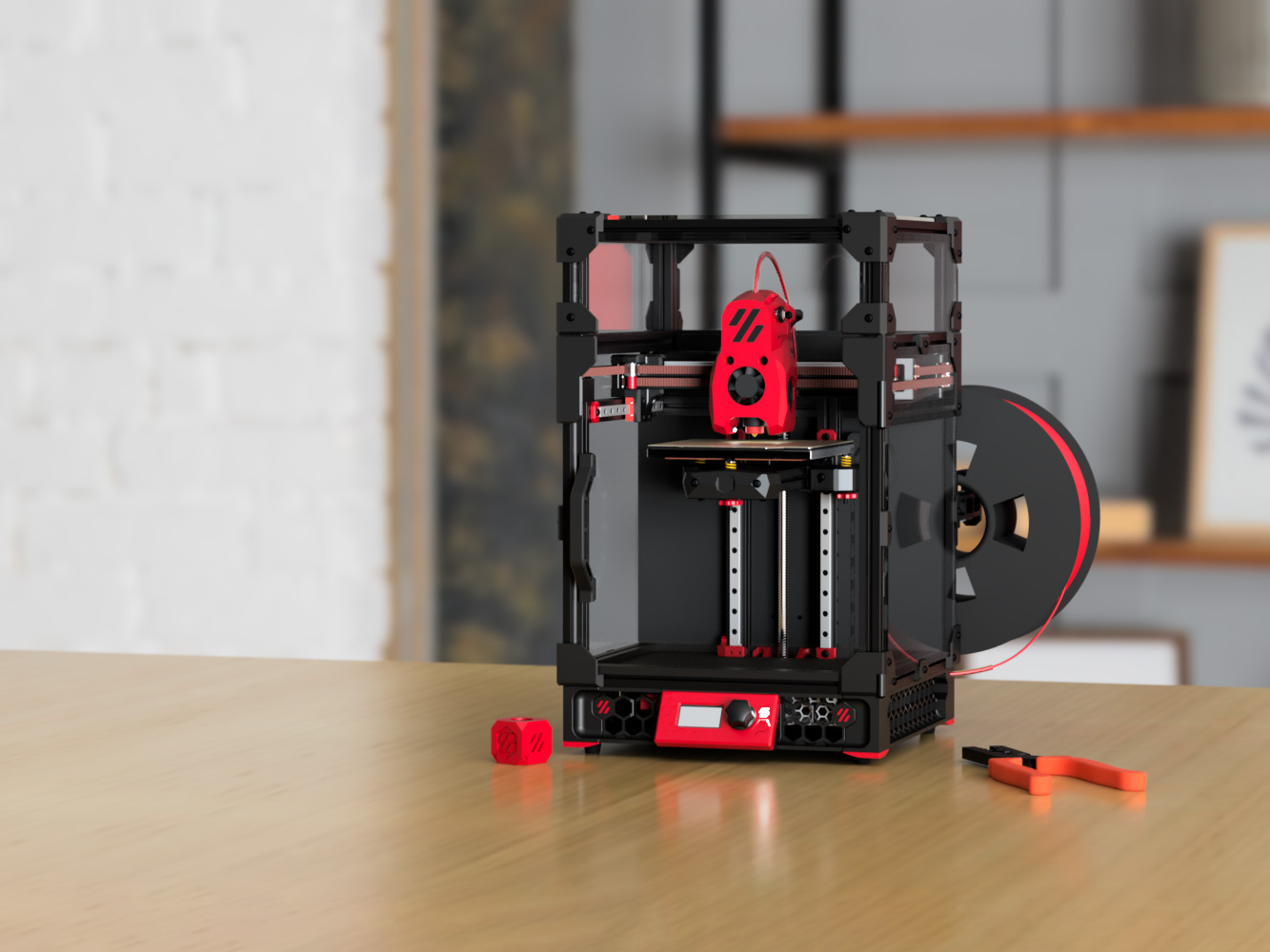
The official release of the Voron Zero 3D printer. You can find the BOM in the configurator located at the Voron Design website.

The current revision is V0.2r1

Highlights

  • Compact and portable
  • 120x120x120 build volume
  • CoreXY
  • Low mass direct drive extruder
  • Enclosed chamber
  • 24v DC bed
  • Klipper firmware
  • Filament runout sensor

Release History

V0.2r1 (2023 June)

Skirts

  • We fixed the issue where 34mm Z motors didnt fit in the machine with the bottom panel installed, this involved increasing the height of the skirts/feet by 2mm
  • We added a simple filament runout sensor to the rear right foot

Toolhead

  • Mini Stealthburner direct drive and bowden cowling part cooling ducts improved
  • an issue with the guidler being able to pivot in an undesired direction was addressed by tightening the bolt holes to reduce play
  • RIDGA support for the bearings that come stock with the ridga kit has been added

Tophat

  • cam locks for the tophat were changed to a simple hex key design

Z Endstop

  • z endstop mount was beefed up to improve ridgidity

BOM Changes

the BOM increased by the following items

  • 2x m2x10 self tapping screw
  • 1x MR85 bearing
  • 1x Microswitch
  • 1x ECAS04 Bowden Collet

V0.2 (2023 January)

A majority of the printed parts have changed. The configurator will give you an idea of parts needed if you are upgrading from V0.1.

Toolhead

  • New design: Mini Stealthburner
  • Direct Drive Extruder with BMG gears and 20mm thick pancake motor with 10 tooth spur gear
  • Improved part cooling ducts (fans are same as V0.1)
  • Supports Revo VORON, Dragon, Dragonfly BMO, DropEffect XG, Creality Spider Pro

Drive units

  • Motor screw count reduction
  • Endstop removed for sensorless homing

Frame

  • No changes

Tophat

  • All panels have changed
  • All side panels are identical
  • Extrusion based tophat
  • Hinged design
  • Cam locks to secure tophat in place

Panels/Clips

  • All panels are 3mm
  • Deck panel changed, new panel is not required
  • Split rear panel

X/Y Joints

  • Tops became 1mm smaller to accommodate MiniSB
  • Endstop block removed for sensorless homing

Bed Assembly

  • Printed parts changed, bed position moved 3mm to the rear

Feet/Skirts

  • Trident skirt community mod folded into official release

Front Idlers

  • Cam locks added

V0.1 Inital release (2021 April)

See https://github.com/VoronDesign/Voron-0/releases/tag/V0.1

V0.0 Updates and fixes (2020 Sept)

See https://github.com/VoronDesign/Voron-0/releases/tag/V0.0r1

V0.0 Initial release (2020 April)

See https://github.com/VoronDesign/Voron-0/releases/tag/V0.0

Voron Logo

voron-0's People

Contributors

camerony avatar daschu117 avatar doowrednu avatar dubjay2k avatar dunardolorgiet avatar fheilmann avatar gerogefu avatar hartk1213 avatar john-- avatar kiloqubit avatar kuriohonoo avatar kyleisah avatar maverick-3d avatar meteyou avatar mugenmicko avatar nemgrea avatar newphreak avatar plumpcheek avatar raymondh2 avatar rufo avatar ruiqimao avatar s0urfruit avatar samtny avatar stackingdeezlayers avatar tagslack avatar timmit99 avatar truongdesign avatar voltexrb avatar weaslus avatar zerrafrx avatar

Stargazers

 avatar  avatar  avatar  avatar  avatar  avatar  avatar  avatar  avatar  avatar  avatar  avatar  avatar  avatar  avatar  avatar  avatar  avatar  avatar  avatar  avatar  avatar  avatar  avatar  avatar  avatar  avatar  avatar  avatar  avatar  avatar  avatar  avatar  avatar  avatar  avatar  avatar  avatar  avatar  avatar  avatar  avatar  avatar  avatar  avatar  avatar  avatar  avatar  avatar  avatar  avatar  avatar  avatar  avatar  avatar  avatar  avatar  avatar  avatar  avatar  avatar  avatar  avatar  avatar  avatar  avatar  avatar  avatar  avatar  avatar  avatar  avatar  avatar  avatar  avatar  avatar  avatar  avatar  avatar  avatar  avatar  avatar  avatar  avatar  avatar  avatar  avatar  avatar  avatar  avatar  avatar  avatar  avatar  avatar  avatar  avatar  avatar  avatar  avatar  avatar

Watchers

 avatar  avatar  avatar  avatar  avatar  avatar  avatar  avatar  avatar  avatar  avatar  avatar  avatar  avatar  avatar  avatar  avatar  avatar  avatar  avatar  avatar  avatar  avatar  avatar  avatar  avatar  avatar  avatar  avatar  avatar  avatar  avatar  avatar  avatar  avatar  avatar  avatar  avatar  avatar  avatar  avatar  avatar  avatar  avatar  avatar  avatar  avatar  avatar  avatar  avatar  avatar  avatar  avatar  avatar  avatar  avatar  avatar  avatar  avatar  avatar  avatar  avatar  avatar  avatar  avatar  avatar  avatar  avatar  avatar  avatar  avatar  avatar  avatar  avatar  avatar  avatar  avatar  avatar  avatar  avatar  avatar  avatar  avatar  avatar  avatar  avatar  avatar  avatar  avatar  avatar  avatar  avatar  avatar  avatar  avatar  avatar  avatar  avatar  avatar  avatar

voron-0's Issues

Enclosing the high voltage compartment (bottom)

While the voron v0.1 is a great machine to tinker and build upon, there is a glaring safety issue of the exposed mains voltage compartment. The stock printer should include a solution where one can enclose the bottom with a 230mmx230mm acrylic sheet to keep fingers away whilst handling or moving the machine around.

For experienced users this may not be an issue but considering the popularity of this version many novice tinkerers will build this printer.

Wire length for x endstop is very tight

When wiring the V0.1, the suggest length of 400mm for the wire of the x-endstop seems a bit tight. Adding something like 20mm made it much more comfortable. Would be great to see a slightly longer length suggested!

BOM and Sourcing Guide disagree on wire gauge and length

Sourcing guide says:

Cable Quantity
PTFE Wire 22gauge 100ft (get 5m of 6 colors for 30m total, tin plated) 1
Silicon Wire 18gauge 10ft (individual strand length total [example: 25ft of 4p wire=100ft]) 1

BOM says:

Cable Quantity
Silicon Wire 24gauge 100ft 1

(also, "Silicon wire" should be "Silicone wire")

Adjustment suggestions for the manual

Hello all
First of all I would like to say that I, a CAD designer, am very enthusiastic about this great printer. The parts, as well as the manuals and the community are of high quality and unparalleled.
That's why I want to use my skills as a quality manager and responsible for company standards in my company to make this great project even better. Starting with the manual!
When I assembled my V0, I felt a bit lost in certain parts of the manual.

General hint:

  • That Loctite might react with ABS+ and might not be beneficial in certain places. A note on this might not be so bad, for noobs like me.
  • I would make the text bubbles and their text larger. I'm not the youngest anymore, and would have liked more readable texts. Also, I'm not a fan of white text on an orange background.
  • I would introduce a bubble/color for optional hints. Be it additional M3 nuts for future extensions etc..

Page 6-7

  • I would number the profiles. Because I made the mistake of installing the wrong profile right at the beginning, which is what should be needed with the frame. Of course, I then simply added two holes. But that could have been avoided.

Page 10-11

  • "2x" is not in the same place, on both sides!!!!! 😉

Page 15

  • Bottom left illustration. Write on, nevertheless, please, that one puts a M3 nut under there in each case. I had wondered what it is held by, or if on any other pages this screw is used for something else, because it sits there loosely.

Page 15-16

  • As an optional note, I would add additional M3 nuts lined with foam tape (thanks Christoph Müller#3576 for the tip).
    Anyway, I would be happy if I had received such a tip early enough, and not only when I have assembled everything.

Page 20

  • The title of the page is not aligned correctly.

Page 25

  • A hint as to where the motor cable should look would be nice.

Page 27

  • Backlash nut should be written on. Only at the end of the assembly, did I notice that this was missing. This was probably the worst thing missing from the manual.

Page 29

  • Illustration at top left, "M3*6 BHCS + M3 Groove." Not that people use MakerBeam T-Nuts.

Page 30

  • Foam tape would hold the nuts in place here, making it easier to mount the Z-motormount, but also the backpanel.

Page 34

  • "M3*6 BHCS + M3 Nut."

Page 35-36

  • M3 nuts, secured with foam tape, for future upgrades.

Page 37

  • A measurement with the edge distance would be helpful, not that you tighten the rail in the completely wrong place already.
  • Text "Use Rail Guides to Center Rail" is missing.

Page 74

  • The M3 nuts on both sides of the rail should be listed, noticed they were missing on page 81. Had to take everything apart again.

Page 136-137

  • The cable routing for the front fan, I would draw in better and route it through the notch for the left part fan.

For questions I am also available in Discord
All in all, it was fun to assemble the Voron.

Panel holders dont account for VHB thickness

Hello,
while assembling my panels, i noticed that most panel holders dont sit flush when using regular VHB tape.
The VHB is ~1mm thick, so the Panel holders need a deeper recess.

Setup Guide Startup Pin No Serial Device

The Setup Guide mentions setting !PC13 on startup in the config. On my device with !PC13 the serial port does not appear in /dev and no device is listed in lsusb either.

I resolved the issue above by changing !PC13 to !PA14. I suspect there was a hardware change in revision V2.0?

I'm not familiar with Klipper/SKR, and I can't find a good schematic to validate... Does this sound reasonable?

Upstream reference:
https://github.com/KevinOConnor/klipper/issues/3461

Manual Issue: pocket watch

If somebody is following the main assembly manual, (which is the only manual you get sent to from the website), the Pocketwatch extruder suddenly springs from nowhere, fully assembled on page 67. I think it would avoid some confusion to link the Pocketwatch manual from the website, or from a caption in the manual (or both)

5V Hot End Fan in to 24V FAN0

Hi team,
I crossed this discrepancy by accident while searching for configuration info in Voron Documentation under Voron V0.0 - SKR mini E3 V2.0 Wiring: https://docs.vorondesign.com/build/electrical/v0_miniE3_v20_wiring.html#voron-v00---skr-mini-e3-v20-wiring

Bulit 4; Plug Hot End Fan in to FAN0 (pin PC6), is FAN1 (pin PC7) in the example Github printer.cfg: fa6f00e
Both pins have 24V output.

However, in the Voron sourcing guide, a 3007 axial fan 5V (min 3.5CFM) is specked: https://vorondesign.com/sourcing_guide
Connecting the fan straight to FAN0 or FAN1 will fry your hot end fan. With a lack of +5V outputs, my positive is wired to the probe +5V pin and FAN1 ground. Not sure where that wisdom came from, but I didn't make it up by myself.

Hope this helps making future building experiences even more awesome!

Potential instruction manual build reordering (1)

I found that building most of the frame, then dropping in the z-axis "h" section made life far easier.
Building the assembly that is present on page 33 separately, and then putting together the rest of the v0 frame was far, far faster.

This would involve building the outer 10 extrusions first-- the bottom square (4 extrusions), the top y-axis square (4 extrusions), and the verticals between them.
Once those are built, you can simply slide in the 'H' assembly as appears on page 33 from the back.

Potential instruction manual build reordering (2)

Before putting in the bottom panel, please have the cable-chain stop installed. Doing it later makes it far more difficult to get it in (or to get it snug without stripping a screw-head).

In the current manual, the bottom cable-chain stop should be installed before/with page 36.

Wrong Item on BOM

There is a wrong link on the BOM for the V0. If you are such an idiot like me and the list is not matched one to one with the link. One notices that a SHCS is needed, but a link for a BHCS is given ( https://de.aliexpress.com/item/4000888328429.html?aff_platform=portals-tool&sk=_d6yFG2z&aff_trace_key=a60eee5776474516bf270c003d9f5819-1608719124758-01673-_d6yFG2z&terminal_id=faa6ce545a8f47138c9c28b594715983&tmLog=new_Detail ). Now it is still such a snap measure of M2.5 that I do not have lying around. Now I have to turn the head of a BHCS. But I think that would have been preventable :<

Image of BOM

Manual: Move mention of nut usage

On page 16 in the manual you're told to install the rail stoppers, but there's no mention of nuts being shown before page 18. Makes more sense to mention it the first place you use them. Props to setyte#5616 @ discord

Incorrect Stealthchop Setting in the Default Config

There is quite a lot of discussion on Discord right now, with people having problems with the wrong default setting in the repo. This has lead to many turning off Stealthchop entirely, meaning they will not benefit from near-silent - and skip free - steppers.

Klipper docs are fairly clear that Stealthchop should either be always on, or always off:

Enabling "Stealthchop" mode

By default, Klipper places the TMC drivers in "spreadcycle" mode. If the driver supports "stealthchop" then it can be enabled by adding stealthchop_threshold: 999999 to the TMC config section.

It is recommended to always use "spreadcycle" mode (by not specifying stealthchop_threshold) or to always use "stealthchop" mode (by setting stealthchop_threshold to 999999). Unfortunately, the drivers often produce poor and confusing results if the mode changes while the motor is at a non-zero velocity.

So I would suggest changing the default configuration for stepper_x, stepper_y and stepper_z to:

stealthchop_threshold: 999999 # Comment out to turn off StealthChop

I doubt that using Stealthchop on the extruder motor is going to provide any benefit, and because it can reduce the motor torque at higher speed it may cause problems. I would suggest turning it off for the extruder.

Model of printer not mentioned until late in the manual

This is by no means critical, but it is amusing!

The first mention of "v0" is on page 86, and the first mention of "v0.1" is on page 132.

Would be nice to have this on an earlier page for those of us who mess up the naming of the downloaded file!

Problem in Downloading some .stl´s

There is a problem in downloading the following .stl´s:

  • PSU_cover_x1.stl
  • Power_Inlet_x1.stl
  • Raspberry_Pi_3b_Mount_x1.stl
  • Rear_Bed_Mount_Left_x1.stl
  • Rear_Bed_Mount_Right_x1.stl

Can´t download them because after a click on the download button, it opens the file as a txt-file.
PSU_cover_x1.stl doesn´t even offer a download button

Recommend revisions to V0.1 bed construction

Having gone through a couple rebuilds of my bed, I'd like to offer a few suggestions for refinement:

  1. Ditch the printed thumb knobs and go back to the knurled metal nuts from V0.0.
  2. The Z adjustment screw hole strips out quickly. Thicker walls or something might help.
  3. Put washers between the springs and lock nuts to keep them from getting cockeyed and buckling. I had a bad problem with mine shifting around on the nuts while adjusting. Adding a washer gave them a flat surface to push against.
  4. Make the holes for the springs a bit shallower. That gives them a bit more tension at a given height making adjustments more reliable and gives a wider usable range.

Is it possible to scale to 2020 extrusion? (was: 4040)

1515 extrusion is not available worldwide. There is no equivalent of McMaster-Carr or Misumi outside the USA. It's extremely expensive to have shipped internationally too.

4040 extrusion is metric, easy to find pretty much anywhere, and less than 2mm larger.

Is it possible to scale the printed parts to account for this?

Also I hope if there is a 1.0 (or 2.0) version, this is taken into account and revised for the more standard size.

Wire colors for E-Motor don't match BOM-specified part.

With the BOM/Sourcing-guide specified LDO 36STH17-1004AHG stepper for the extruder (E-motor), the wiring color should be green-red-blue-yellow (this should be tested, but at least this makes the motor move, instead of just buzzing).

Any idea when the CAD will be released?

Quite keen to try the new direct drive hotend design, but I need to make some modifications. Doing those on STL can be a pain in the ass. Any chance of releasing the CAD?

Assembly Manual is corrupt

Manual updated 2 hours ago won't open. Adobe reports the file is corrupt.
Tried downloading twice, deleting file in-between.

FR : More FDM friendly tophat parts

Hello, sorry if this is not the right place to request FR like this.
The chamfer on the top hat parts is 36.78° that make the parts very hard to print nicely with FDM printer. At first, I was thinking problem is my bad cooling, but other members on Voron discord also have the same problem, some suggest to print the parts with PLA+. If the chamfer angle is 45° or higher, the parts will can be printed with most of filament type.
tophat

Gaps in Toolhead Blower Duct (Left)

Thin walls around the screw holes on the part: "[a]_Toolhead_Blower_Duct_Left_TV6_x1" leads to gaps on the inside during slicing and printing. Attempted to alleviate the issue by enabling "Print Thin Walls" within Cura, to no avail.

Printed using recommended settings, please see attached for reference.

20200905_140744

image0

unknown

Panel mounting clip STLs: incorrect part depth?

About half the "3mm" set of panel clips have 5mm depth and fit my 3mm panel nicely, including room for VHB tape. The other half have 4mm depth and as a result have an awkward fit, requiring either loose tension of screws or some "flexing" of the clip to meet the rail.

The list of parts in the "3mm" set that have 4mm (perhaps incorrect?) depth is:

  • 3mm_Bottom_Corner_Side_mirror_x1.stl
  • 3mm_Bottom_Corner_Side_x2.stl
  • 3mm_Middle_Clip_x9.stl
  • 3mm_Top_Corner_Rear_mirror_x1.stl
  • 3mm_Top_Corner_Rear_x1.stl
  • 3mm_Top_Corner_Side_mirror_x1.stl
  • 3mm_Top_Corner_Side_x2.stl

One way or the other, the fitment of the parts in this STL set seems to me inconsistent.

Insufficient m3x6 screws in the BOM

Hi. The BOM requires 11 m3x6 screws which is not sufficient. Only the skirts need 12 of them. Also there is a related mistake in the manual, where m3x35 and rubber feet are listed instead of m3x6.
image

BOM discrepancy?

BOM calls for "Bondtech Motor Gear" but it is unnecessary because the spec'd stepper already has a gear

Zip ties missing from BOM

Assembly requires zip ties in various locations, but they're not included in the BOM.

... And since some of the parts require smaller zip-ties than people are likely to have (smaller than 4in/100mm, which are typically the smallest in normal zip-tie assortments), it is worth a call-out somewhere like the BOM/sourcing guide!

Make manual a bit more clear

Please update the manual to state type of fans used.

For example in section where mini afterburner assembly is described (page 105), switch "Axial Fan" to "3007 Axial Fan".
I mean in the same way how bolts are described on every single page.

BTW this particular axial fan is of new type, 3010 from V0 can not be used here. As for now this is not stated anywhere aparat of the discord answer to my question :)

Wiring diagrams inconsistent colors

The wiring colors on page 135 are inconsistent-- A motor has red-black-blue-green, but should be black-green-red-blue (as is true of the other motors on that page). Two pages later, page 137 has the correct wire colors for the A motor.

PrusaSlicer Profile extrusion width

The extrusion width percentages in the PrusaSlicer profile seem to be based on Nozzle diameter, like SuperSlicer does.
PrusaSlicer calculates them on Layer height.

30mm blower fans sensitive to the hotend heat and stops working

The BOM specified GDSTime 24v 30mm blower fans used for the Part cooling fans are susceptible to overheating from being in close proximity to the hotend.

Observed behaviour;

  • When the hotend is hot the fan on the side of where the heater cartidge tip is visible, ossilates and doesnt spin
  • When cooled down or when the hotend is not driven the fan spins as expected.
  • The other part cooling fan spins normally.

Potential fixes;

  • A not so temprature sensetive blower fan
  • Somehow isolating the heat of the hotend from the fan hub.

Also asking for potential workarounds and/or solutions.

about [a]_Cowling_Mosquito_MULTIBODY_x1.STL

compare with the multibody for dragon, i found there's a mistake with this [a]_Cowling_Mosquito_MULTIBODY_x1. There is not enough space to add the 3007 fan . but there is a concave place on the top of the Dragon_Toolhead_DD or Dragonfly_BMO_Toolhead_DD stl, just fit for 3007 fan.

Inconsistent screw lengths in the assembly manual

The screw lengths in the pictures do not match the screws listed in the bottom right corner on p.104, p.106, and p.108.

I guess that the 6mm screws will be used for 2.5mm thick panels and the 8mm screws for the 3mm panels. Maybe that can be also mentioned somewhere in the manual. (The same goes for the ABS panel on p.33)

A magnet sheet is not included in the BOM

I think the magnet sheet should have its own line in the BOM separate to the "Spring Steel Flex Buildplate 120x120mm (OPTIONAL)", especially given that the sourcing guide recommends buying a better quality sheet than the ones that can be bundled with the spring steel plate:

"base" refers to the magnet which is not very good, better to buy a stronger 3rd party one

Firmware/printer.cfg needs run current changes, too high for OMC Z-axis motors

[tmc2209 stepper_z]
uart_pin: PC11
tx_pin: PC10
uart_address: 1
interpolate: True
run_current: 0.37       # For V0.1 spec NEMA17 w/ integrated lead screw   
hold_current: 0.35
sense_resistor: 0.110
stealthchop_threshold: 500

The run_current: 037 is fine for the LDO-42STH25-1004CL200E 1.0A, but is over the 0.28A max for the OMC 17LS13-0404E-200G 0.4A

Perhaps having two different configs in [tmc2209 stepper_z], with the OMC being commented out by default, but adding additional commenting to inform the user.

I've added an example below as well as included all of the current BOM motors and their currents in case that information was helpful or if you wanted to incorporate them as comments into the config.

[tmc2209 stepper_z]
uart_pin: PC11
tx_pin: PC10
uart_address: 1
interpolate: True
#run_current: 0.37       # For V0.1 spec NEMA17 LDO-42STH25-1004CL200E 1.0A  
#hold_current: 0.35
run_current: 0.2         # For V0.1 spec NEMA17 OMC 17LS13-0404E-200G 0.4A 
hold_current: 0.15
sense_resistor: 0.110
stealthchop_threshold: 500

[tmc2209 stepper_x], [tmc2209 stepper_y]
OMC 14HS20-1504S 1.5A
LDO N/A

[tmc2209 stepper_z]
OMC 17LS13-0404E-200G 0.4A
LDO-42STH25-1004CL200E 1.0A

[tmc2209 extruder]
OMC 14HR07-1004VRN 1.0A
LDO-36STH17-1004AH 1.0A

Deck panel rear DXF missing segments

I'm loading it into Freecad 0.18.4, and there are two curves missing, not sure if this is a FreeCAD bug or not, but the middle back plate loaded fine.

It's the two curves that connect the z-carriage inset. --\___/--

ta

inset

Dragon Hotend Mounting

The screws in the CAD are modeled as M2.5 x 12mm, but the stock Dragon Hotend (at least from Phaetus) comes with M2.5x8mm. The V0 BOM doesn't call for M2.5x12mm screws, and the Toolhead holes for mounting the hotend have 9mm of through depth :(

Recommend Projects

  • React photo React

    A declarative, efficient, and flexible JavaScript library for building user interfaces.

  • Vue.js photo Vue.js

    🖖 Vue.js is a progressive, incrementally-adoptable JavaScript framework for building UI on the web.

  • Typescript photo Typescript

    TypeScript is a superset of JavaScript that compiles to clean JavaScript output.

  • TensorFlow photo TensorFlow

    An Open Source Machine Learning Framework for Everyone

  • Django photo Django

    The Web framework for perfectionists with deadlines.

  • D3 photo D3

    Bring data to life with SVG, Canvas and HTML. 📊📈🎉

Recommend Topics

  • javascript

    JavaScript (JS) is a lightweight interpreted programming language with first-class functions.

  • web

    Some thing interesting about web. New door for the world.

  • server

    A server is a program made to process requests and deliver data to clients.

  • Machine learning

    Machine learning is a way of modeling and interpreting data that allows a piece of software to respond intelligently.

  • Game

    Some thing interesting about game, make everyone happy.

Recommend Org

  • Facebook photo Facebook

    We are working to build community through open source technology. NB: members must have two-factor auth.

  • Microsoft photo Microsoft

    Open source projects and samples from Microsoft.

  • Google photo Google

    Google ❤️ Open Source for everyone.

  • D3 photo D3

    Data-Driven Documents codes.