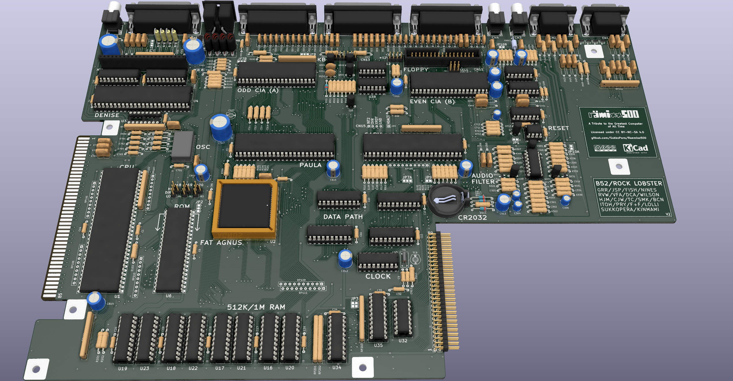
Rämixx500 is an Open Hardware remake of the Commodore Amiga 500+ mainboard, revision 8A.1.
Many Amiga 500+ computers are suffering an early death because of the built-in barrel battery that powers their internal real-time clocks. Such batteries have long exceeded their planned lives and in many cases have started to leak alkaline liquids over the mainboard, corroding copper traces and destroying components.
This damage can sometimes be repaired trivially, but many times it requires a lot of time and effort. Sometimes it adds up to other damage occurred over time and so it would just be better to have a new board built with new components to move the few critical chips over. Amiga mainboards haven't been produced for the last 30 years, but they are relatively simple by today's standards, thus an amateur project to make new ones was started.
There are other projects with the same goal out there, but none of them is Open Source and none of them comes with both schematics and board. This is a big advantage, since anyone can modify the board and make new improved versions, as long as they release their modifications it with the same license. I have come up with some ideas for improvements, feel free to help :).
The first version of the board was released in April 2020 as untested, in the hope that someone from the Amiga "Community" would jump in and help with the testing. Well, that took quite some time but in the end someone finally understood that Open Hardware is about trying to do your part rather than coming up with heaps of useless talking and moaning or blatant stealing and allowed this project to reach the next milestone. So despite knowing he could be jumping into the void, fellow Italian living in Japan Edoardo Auteri put confidence, money, time and effort into assembling a board and testing it thoroughly. While he was at it, he came up with some interesting ideas which ultimately encouraged me to make Version 2, which fully passed all tests. You can read more about the development and testing of the board on the official development blog.
The initial objective was to come up with a new mainboard as similar to the original one as possible, while including minor modifications that would improve its usability. This mainboard was designed with reasonable - not maniacal - accuracy to the original design. Most care was taken in the positioning of components that ought to be in a certain position (i.e.: screw holes and I/O connectors), to ensure drop-in replaceability. Other components and tracks are "more or less" there, but as the board was wholly laid out from scratch by hand, don't expect sub-millimeter accuracy.
Some modifications were soon added in, in the hope that they would be useful. Let's make it clear straight from the beginning that most of these improvements and modifications are completely optional and actually disabled by default. This means that you can just ignore them and everything will work as it did on the original A500+ board. If you want to take advantage of them instead, you will need to do some work.
-
Buffered Video Synchronization Signals: This will make the VSYNC and HSYNC signals going out from the DB23 connector somewhat "stronger", which should improve video quality and also allow using fully passive (i.e.: just wires) RGB to VGA cables (but please note that the signal will still be 15 kHz so a scandoubler will still be required with most VGA monitors). To enable this, cut both the JP99H/V jumpers, solder a 74HCT14 SOIC chip at U94 (yes, it's surface-mount, but the available space was limited) and a 100-330nF ceramic capacitor at C94. Note that if you want to get back to unbuffered (why???) you will both need to unsolder U94 and close the jumpers again, otherwise you will definitely damage your Denise and/or buffer. One small caveat: you'd better decide what to do with this mod before you solder the nearby components, as space around U94 is really tight and (un)soldering it with the other components in place is not a task for the faint-hearted.
-
ESD Protection for the Joystick Ports: While connecting controllers blindly is still not recommended, you can add some diodes that should hopefully avoid damage to the internal chips whenever you do so. These won't hurt in any case, so why not? Just solder some AT1042 chips at U90-U93. Yes, they are small but you can make it.
-
Hard Disk LED: If you use an internal expansion board that provides an IDE connector, you will feel the need for a LED flashing whenever the disk is accessed. If you connect a wire from pin 39 of your CF adapter to the new HDACT connector right in the middle of the board, the Floppy light will also flash when the hard disk is accessed. To get this to work, solder a 2n3906 transistor at Q99 and resistors R98 (10k) and R99 (4.7k).
-
Alternative Footprint for the Line Filter: The original line filter (LF1) was probably a custom part, but in any case it's impossible to find these days. Luckily a functionally-equivalent part is available (Laird Z131B-10) but it has a different footprint, so the latter was added at LF99. Be very careful when soldering this, as it is very easy to make a solder bridge between the pads of LF1 and those of LF99 and short out the power rails.
-
Alternative SMD Footprints for the JFETs: Q321/331 are a bit hard to find these days in the TO-92 package, so alternative surface-mount SOT-23 footprints were added (Q921/931). Choose the package you prefer and only solder one of each.
-
More Accurate Dimensions: While V1 was already pretty close to the original board, the new version should be right on the money. Placement of the audio and mouse ports was also improved.
-
More Detailed Silkscreen: The values of all resistors, capacitors and chips are now printed on the silkscreen, which makes the assembly process quicker and less error-prone.
-
Improved Routing and Ground Plane: Some tracks were slightly altered in the hope of achieving improved signal integrity. Lower impedance to ground also resulted in all chips running a few degrees Celsius colder.
-
One more change lies in the license: the project is now released under CC BY-NC-SA, which is not too different in practice from the license we were using before, except that any commercial use is now prohibited. I know this makes the project non-free, strictly speaking. While I am sorry for that, that's what the behaviour of the "community" has led me to. Blame them, not me.
-
Support for VBB Agnus: This board is compatible with a few different Fat Agnus models, namely: 318069-10 and 390544-03 for PAL or -11 and -02 for NTSC (FIXME). The 390544 models have a VBB marking and require a 100-330nF cap to be fitted at C99, which must instead be left unpopulated for the other models. Note that while all the mentioned models are also numbered 8375, not all 8375 models are actually compatible: please check that the extended part number is one of those mentioned above (these usually came from "wide label" A500 featuring a Rev.8A mainboard, A500+ or A600 computers, if you got your Agnus somewhere else, it likely isn't the correct one). 8372 and 8371 models are definitely not compatible either at the moment. And before you ask: no, Alice chips will never work.
-
Mono Audio Link: This feature was lifted from the A600/A1200 and will transparently downmix the audio output to mono whenever you only plug one of the two audio connectors (any of the two), while on the original A500 you would only hear the corresponding channel. Whenever you plug both connectors, the channels will separate automatically. This is the reason why this feature is enabled by default, in that it is completely transparent to the user in normal conditions.
-
Alternative Power Connector: Besides using the original A500 power connector, which can be expensive to get hold of, you can use common and cheap DIN-6 or DIN-8 connectors. Have a look at the wiki for more information, including a wiring method.
-
Kickstart Switcher: This is a set of jumpers that will allow you to store more than one Kickstart image on a single ROM chip and enable one at will. If you want to use it, have a look at the wiki.
-
Drive Switcher: This is a pretty basic drive switcher which will result in the first external drive to be seen as DF0: and the actual DF0: to become invisible. Instructions for how to use it are on the wiki as usual.
Following is a list of deliberate changes with respect to the original layout of the A500+ rev.8A.1 board:
- The footprints for all DIP chips use "long pads". This makes them easier to solder and more solid to the board should you need to rework them. This forced a few tracks running very close to the original pads to be slightly offset away.
- The power connector footprint was altered to either accept the original connector, a DIN-6 or a DIN-8. I actually recommend the latter, as it uses more than one pin for the +5V and +12V rails, allowing for more current.
- The floppy connector footprint was changed to that of a full IDC connector.
- The barrel battery was replaced with a BS-7 battery holder for a normal (non-rechargeable) CR2032 battery. Consequently, R913 has been replaced with a diode (labeled D913) and a couple of tracks needed some displacement.
- The need to solder D912 to a leg of the former R913 has been removed. Just solder it in its place.
- The RCA jacks for the audio and composite video outputs have been replaced with some that can actually be found nowadays (i.e.: those that were used on A600/A1200). This resulted in having to relocate R409 (whose original position seemed somehow improvised anyway...).
- The silkscreen for some components does not match the original one. I used the built-in KiCad footprints as-is, when available.
- The silkscreen and pitch of C303, C304 and C306 have been made smaller so that they don't overlap.
- Speaking about the silkscreen, I have been quite liberal with it. I have used the default KiCad font and I did not follow the original label placement at all costs. I did this since today's technology can give us a bit more resolution in silkscreen printing, and I think that is worth using for the sake of clarity. Some ground stitching vias were slightly offset to make up space for labels.
- The vias inside the pads of JP10A and JP11 have been slightly offset so that they are outside the pads.
- The ground fill is autogenerated by KiCad, so it won't match the original exactly.
- Probably there's something more I've forgotten.
Please refer to the wiki.
If you want to get this board produced, you are recommended to get the latest release rather than the current git version, as the latter might be under development and is not guaranteed to be working.
Every release is accompanied by its Bill Of Materials (BOM) file and any relevant notes about it, which you are recommended to read carefully.
I am not providing ready-to-use gerber files. If all you want is to get boards made, I would really appreciate if you did so in a way that supports the project.
The Rämixx500 documentation, including the design itself, is copyright © SukkoPera 2019-2021 and is licensed under the Creative Commons Attribution-NonCommercial-ShareAlike 4.0 International License.
This documentation is distributed as is and WITHOUT ANY EXPRESS OR IMPLIED WARRANTIES whatsoever with respect to its functionality, operability or use, including, without limitation, any implied warranties OF MERCHANTABILITY, SATISFACTORY QUALITY, FITNESS FOR A PARTICULAR PURPOSE or infringement. We expressly disclaim any liability whatsoever for any direct, indirect, consequential, incidental or special damages, including, without limitation, lost revenues, lost profits, losses resulting from business interruption or loss of data, regardless of the form of action or legal theory under which the liability may be asserted, even if advised of the possibility or likelihood of such damages.
This said, I would like this project to progress further. If anyone would like to do major work on it but is discouraged to do so by the impossibility to exploit the work commercially, please get in touch with me, I will grant you a private license which will allow you to do that.
If you are interested in getting a single board, you can get it from one of the official sellers:
- EU: Sordan
- UK: Simulant (link coming soon)
(If other sellers want to become "official", just get in touch with me.)
These are well-known and trustworhty sellers, who keep a fair price and even donate part of their earnings towards the development of the project, so please buy from them if you can.
If you want to get several boards, you can get them made from PCBWay through this link:

You get my gratitude and cheap, professionally-made and good quality PCBs, I get some credit that will help with this and other projects. You won't even have to worry about the various PCB options, it's all pre-configured for you!
Also, if you still have to register, you can use this link to get some bonus initial credit (and yield me some more).
You can also buy me a coffee if you want:
- Commodore, for making the coolest machine ever.
- Edoardo Auteri for putting confidence in me and joining the project. He is also the person that you should be thankful to if this project is still open-source.
- Amiga PCB Explorer, a fundamental tool to follow the original track placement.
- amigawiki, mainly for the schematics but also for the whole lot of information they provide.
- majinga for helping with the measuring.
- Walter for some of the footprints/3D models used.
- DiagROM for inspiring the selling clause.
- Jason Warnes for information about the original power connector and how to replace it with a DIN-8.
- Szabó Zoltán for designing the board logo.
- Workshopshed for the 3D models of the EMI filters.
- StormTrooper for a few other 3D models, taken from his Plus/4 remake.


