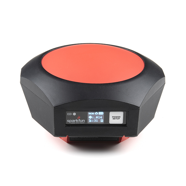
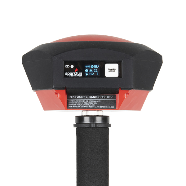
Code Monkey home page Code Monkey logo

sparkfun_rtk_facet's Introduction

SparkFun RTK Facet

SparkFun RTK Facet L-Band (GPS-20000) SparkFun RTK Facet (GPS-19029)

The SparkFun RTK Facet and RTK Facet L-Band are your one stop shop for high precision geolocation and surveying needs. For basic users, it’s incredibly easy to get up and running and for advanced users, the RTK Facet is a flexible and powerful tool. With just a few minutes of setup, the RTK Facet is one of the fastest ways to take centimeter grade measurements. By connecting your phone to the RTK Facet over Bluetooth, your phone can act as the radio link to provide correction data as well as receive the NMEA output from the device. This is exactly how $10,000 surveying devices have been operating for the past decade - we just made it easier, smaller, and a lot cheaper.

The RTK Facet L-Band utilizes corrections from u-blox's PointPerfect service broadcast from a geosynchronous Inmarsat satellite. The only setup required is a WiFi SSID and password. Once entered, the device will provision itself and periodically (once a month) update the decryption keys necessary to use the PointPerfect service. The price of the RTK Facet L-Band includes a 12-month subscription. Additional years of service can be purchased.

Under the hood of the SparkFun RTK Facet is an ESP32 WROOM connected to a ZED-F9P as well as some peripheral hardware (OLED, LiPo fuel gauge, microSD, etc). Additionally, housed under the dome of the RTK Facet is a surveyor grade L1/L2 antenna. It is the same element found within our GNSS Multi-Band L1/L2 Surveying Antenna.

Under the hood of the SparkFun RTK Facet L-Band is an ESP32 WROOM connected to a ZED-F9P GNSS receiver, a NEO-D9S L-Band receiver (for corrections), and a variety of peripheral hardware (LiPo fuel gauge, microSD, etc). Additionally, housed under the dome of the RTK Facet L-Band is a surveyor grade L1/L2/L-Band antenna. This antenna is a unique combination of elements designed to receive the GNSS signals (L1/L2) alongside the 1.55GHz PointPerfect corrections. The built-in antenna has an ARP of 69mm from the base to the measuring point of the L1 antenna and an ARP of 68mm to the measuring point of the L2 antenna. The RTK Facet L-Band is programmed in Arduino and can be tailored by you to fit whatever your needs may be.

Repository Contents

  • /Documents - Datasheets and additional product information
  • /Hardware - Eagle PCB files
  • /Labels - Display overlay and info stickers
  • /Mechanical - Drawings use to created injection molding tooling

Documentation

License Information

This product is open source!

Please review the LICENSE.md file for license information.

If you have any questions or concerns on licensing, please contact technical support on our SparkFun forums.

Distributed as-is; no warranty is given.

  • Your friends at SparkFun.

sparkfun_rtk_facet's People

Contributors

bboyho avatar loricrotser avatar npoole avatar nseidle avatar paulzc avatar

Stargazers

 avatar  avatar  avatar  avatar  avatar  avatar  avatar  avatar  avatar  avatar  avatar  avatar  avatar  avatar  avatar  avatar  avatar  avatar

Watchers

 avatar  avatar  avatar  avatar  avatar  avatar  avatar

sparkfun_rtk_facet's Issues

Front Panel should be on the North side

The front panel - the man-machine interface (MMI) - should be on the north side of the unit, with respect to the antenna calibration.

Almost universally, GNSS receivers with integrated antennas are calibrated with the MMI being the north reference point. It is confusing to surveyors that the Sparkfun units are an exception to this widely-followed convention. The unique orientation of the Facets makes it more likely that surveyors will mis-align the Facet when setting up a base or collecting static data.

Besides convention, there is a good reason for having the MMI on the north of the receiver.

The sun, for people in the north hemisphere, doesn't shine from the north. If the MMI is on the north side of the GNSS receiver, it is easier to read and less likely to be washed out by the sunshine. There are more people living in the north vs the south hemisphere, so putting the MMI on the north side of the receiver maximizes the MMI visibility for more people.

See also issue #12.

Facet screw holes are too narrow for many small screwdrivers.

The screw holes for the screws that hold the Facet (GPS-19029) housing together are too narrow to allow most of my small screwdrivers to reach the screw. These are screw drivers that properly fit the screw heads.

This is important as I need to open the case in the field to retrieve lost SD cards.

Radio and Data JST connectors appear incorrectly drawn on External Connector Board schematic

As linked to from the Facet product page
https://www.sparkfun.com/products/19984
I'm looking at
https://cdn.sparkfun.com/assets/d/2/a/b/0/SparkFun_RTK_Facet_-_External_Connector_Schematic.pdf
With a rev date in the title block of "12/3/2021 11:58am" and a version of "V12".

In the section of the schematic showing what I believe to be the JST Radio and Data connectors, I have the following observations:

  1. I believe the "Serial Config, NMEA Out" connector is what the hookup guide calls the "Data" connector, but this isn't explicit.

  2. The hookup guide doesn't mention using the Data connector for Serial Configuration. I always use the USB-C for serial configuration. The schematic calls it a "Serial Config..." connector.

  3. Why are there two "Serial Config, NMEA Out" connectors on the schematic with the pin numbers flipped?

  4. I believe the "External Radio, RTCM In/Out" connector to be the "Radio" connector as described in the hookup guide. Not explicit but close enough to be obvious.

  5. Why are there two "External Radio, RTCM In/Out" connectors on the schematic with the pin numbers flipped?

  6. According to the hookup guide, the V+ pin on both the radio and the data connector are current limited by a PTC to 600ma. Do both connectors share the same PTC (F1) ? That is, is the sum of the V+ current provided by the data and radio connectors limited to 600mA? This isn't explicit in the hookup guide and the schematic is unclear on this point.

I'm able to make the cables I need using the info in the hookup guide, so the issue is not an impediment for me.

Front panel needs to be visible from below and in bright sunlight.

Front panel and operation status LEDs need to be visible from below and in bright sunlight.

Units from other vendors generally angle the front panel downward, design the case so the LEDs are visible from directly below, and/or use very bright LEDs.

See also #10.

Emlid RS2 - panel angled downward.
image

Trimble R12i - bright and large LEDs visible from directly below.
image

Topcon - front panel angled downward.
image

Carlson BRx5: Very bright LEDs and nothing on the case to block LED visibility from directly below. The LEDs protrude slightly to aid visibility from below.

image

Facet rests on and bends USB cable when on a table

Performing logging tests here on the firmware. Have the Facet plugged into power. Sitting on my kitchen table at a tilt because it is resting it's weight on the USB cable.

I spend more time learning, debugging, and upgrading this device than actually using it. Therefore having it on my desk with a USB cable plugged in for power or serial IS IN FACT my primary use case :)

T.

Replace Facet 4-pin JST radio connector

The 4-pin JST-GH Radio port connector on the Facet is both less common, difficult to make or source cables, and fragile. The TTL serial levels are fine for drone telemetry-style radios, but do not work with more powerful radios commonly used in the surveying industry. In the field, small tree branches pull on the tiny wires and yank the pins out of the JST connector shells.

I suggest replacing it with a more common connector and/or a more robust connector for which cables are readily available and/or easily constructed. The TTL vs RS232 level issue needs discussion too.

If one is using serial telemetry radios (eg SparkFun LoRa Serial, Holybro, or RFD900 radios), the 4-pin to 6-pin cables are less common. I've had to purchase drone cable kits and frankenstein cables by swapping shells when Sparkfun is out of stock on the 4-pin to 6-pin JST cables.

The simplest but less robust change would be to replace the current 4-pin JST radio connector with the more common 6-pin version. It seems the drone community has settled on 6-pin connectors for telemetry radios and 6-pin to 6-pin cables are commonly stocked by multiple vendors and are also commonly included in cable kits sold for drone builds.

If one is using more powerful radios, building a custom cable is time consuming, and almost without exception the more robust cables used for more powerful radios put a lot of weight on the JST connector....and out comes the duck tape. Yuck.

More powerful radios generally required RS232 levels, so I find myself making cables with the SparkFun Max3232 breakout board incorporated into the cable. Not hard but very time consuming. In the surveying industry, generally the more powerful radios have a DB9 (RS232) cable available.

For the more powerful radios used in the surveying industry, a solution that can be used to connect the Facet to an external radio using a DB9/RS232 connector would be very welcome.

Other options for the radio port include

  • USB: As far as I can tell, every vendor of 900MHz telemetry radios seems to include a USB port or a USB cable with their radios. Robust enough, well-proven, common, easy to get cables for. Not terribly expensive. But the Facet would need to be a USB host. There are USB to TTL serial and USB to RS232 serial cable available.
  • LEMO style connectors. Common in the surveying industry. Very robust. Expensive and hard to for a hobbyist to source parts to build cables for. But widely used in the surveying industry
  • RJ connector. Very inexpensive and cables can be made with $15 tools. Most of us have made these cables for telephony and network applications. Cisco network devices have used RJ connectors for serial consoles 'back in the day' so these cables are widely available. Would need to be RS232 levels.

Add highly visible indicator that logging to SD is active.

Add a highly-visible indicator, observable from below, which shows that logging writes to the SD card are happening.

Static logging is a long-term operation, 2, 4, or even 8 hours. It is important to be able to verify that logging is actually happening after the Facet is setup. It is disheartening to find a setting was misconfigured or even the SD card wasn't properly inserted.

While the logging icon on the OLED display is very useful, the OLED display is often not visible.

  1. It is very common to have a GNSS receiver up on a 2m pole. It's not uncommon for the pole to be on a mark that is projecting 0.2m above the ground. That puts the OLED display over 2.2m up in the air, well above eye level for most people.
  2. The OLED display is easily washed out in bright sunshine.
  3. The OLED display is slightly recessed, making it harder to read from low vertical angles. This is good as it protects the display, but the logging icon in in the lower part of the display.

Many commercial survey GNSS receivers use a bright blinking LED to indicate that logging is active. The LED is visible in sunshine and visible from a low vertical angle.

Redesign housing to support Slant Measurements

My Workbench

Facet 19029 (the one before the carrying case)

Feature Request

Redesign the Facet housing to support slant measurements of height above the mark. It's physically impossible to measure directly with a tape measure from a survey mark to the reference point of the GNSS housing (the bottom) when using standard survey tripods (heavy duty "legs", not a pole or bipod setup) due to the width of the head on standard survey tripods.

This is an issue with most commercial survey-grade GNSS receivers. Many commercial survey-grade GNSS receivers provide a secondary measurement mark for "slant measurements", where the tape is held at an angle from the survey mark on the ground to the edge of the diameter of the GNSS receiver. Many commercial survey data collectors allow the input of
a. the slant measurement - the length of the tape at an angle from the survey mark to the "slant" mark on the edge of the receiver.
b. the offset from the slant measurement to the phase center or bottom reference mark (I forget which at the moment.)
c. the diameter of the receiver at the slant measurement mark.
and the data collector uses a simple triangle formula to calculate the actual height of the antenna phase center above the survey mark on the ground.

Specifically, this includes

  1. Increase diameter to allow a tape measure to run in a straight line from the mark to the case without touching survey tripod head or the tribrach. Standard survey tripods ("legs", not a pole & bipod setup) have a wide head and the current housing diameter is too small - one would have to bend the tape. Some manufacturers (eg. the Hemisphere 320/Carlson BRx5 have tabs (aka "ears") on the housing that increase the effective diameter and give clear place to measure from (or even hold the hook on the end of the tape). See Carlson's KB1042 (link below) for a diagram.
  2. Put a slant mark on the housing (that the rubber bumper moves around needs to be resolved.)
  3. Make the bottom of the Facet ROUND so that the slant height can be measured with a tape from any location and have a consistent radius. The current hexagonal bottom means there is no one radius.
  4. Publish the radius of the housing at the slant mark
  5. Publish the vertical offset from the slant mark to the ARP (the Antenna Reference Point, the center of the bottom of the housing; NOT the APC, as the APC moves with frequency and SV elevation and position.)
  6. Create a diagram showing the radius and vertical offset from the slant mark to the ARP.

OR it might be easier to just use a thin round disk of sheet metal with sufficient diameter between the Facet and the Tripod and slant measure to that. Hmmm. Similar to https://www.sparkfun.com/products/17519 (ground plane) but with a hole large enough for the 5/8x11 tripod screw.


References

https://www.ngs.noaa.gov/AERO/Genspecs_A/Volume%20A_Attachment%2011-19.pdf
(Multiple docs in this PDF, Scroll down to "Attachment 13" page 3)

This document contains a great example of a diagram showing the radius and slant offset to the ARP.
https://web.carlsonsw.com/files/knowledgebase/kbase05.php?action=display_topic&topic_id=1042

https://kb.unavco.org/kb/article/introduction-to-gnss-antenna-set-up-methods-for-campaigns-71.html

Add indicator for "External Power Connected"

The green power indicator LED on the FACET only shows when the battery is charging due to external power being supplied.

It would be very useful to have an indicator to show when external power is connected, regardless of the state of the internal battery.

When setting up the base for a long work day, it is often necessary to connect external power, especially if using RTK radios, more especially if the radios are transmitting at more power than 100mW. It is important to be able to confirm that the external power is properly connected to ensure the work day will not be interrupted.

Currently, if the internal battery is fully charged, there is no indicator to confirm that the external power is connected properly. If the user thinks the external power is properly connected, but it actually is not, the base will shutdown midday due to the internal battery depleting, interrupting RTK work and static collection.

Recommend Projects

  • React photo React

    A declarative, efficient, and flexible JavaScript library for building user interfaces.

  • Vue.js photo Vue.js

    πŸ–– Vue.js is a progressive, incrementally-adoptable JavaScript framework for building UI on the web.

  • Typescript photo Typescript

    TypeScript is a superset of JavaScript that compiles to clean JavaScript output.

  • TensorFlow photo TensorFlow

    An Open Source Machine Learning Framework for Everyone

  • Django photo Django

    The Web framework for perfectionists with deadlines.

  • D3 photo D3

    Bring data to life with SVG, Canvas and HTML. πŸ“ŠπŸ“ˆπŸŽ‰

Recommend Topics

  • javascript

    JavaScript (JS) is a lightweight interpreted programming language with first-class functions.

  • web

    Some thing interesting about web. New door for the world.

  • server

    A server is a program made to process requests and deliver data to clients.

  • Machine learning

    Machine learning is a way of modeling and interpreting data that allows a piece of software to respond intelligently.

  • Game

    Some thing interesting about game, make everyone happy.

Recommend Org

  • Facebook photo Facebook

    We are working to build community through open source technology. NB: members must have two-factor auth.

  • Microsoft photo Microsoft

    Open source projects and samples from Microsoft.

  • Google photo Google

    Google ❀️ Open Source for everyone.

  • D3 photo D3

    Data-Driven Documents codes.