Code Monkey home page Code Monkey logo

smartknob's Introduction

SmartKnob

SmartKnob is an open-source input device with software-configurable endstops and virtual detents.

A brushless gimbal motor is paired with a magnetic encoder to provide closed-loop torque feedback control, making it possible to dynamically create and adjust the feel of detents and endstops.

Join the Discord community to discuss the project with others, show off your build, or help answer each others' questions!

Build Status Build Status

Designs

SmartKnob View

The "SmartKnob View" is the premium SmartKnob experience with an integrated display shown in my demo video. Under active development.

๐ŸŽ‰ Motors are now available! If you've been following this project, you'll know that the recommended motors went out of stock nearly immediately after it was published. Thanks to the community, we were able to identify the likely original manufacturer, and recently SparkFun Electronics has been getting them produced and regularly stocking them! (However, they've been selling out quickly each time they restock, so definitely sign up for backorder notifications if they're out of stock when you check). Thanks to everyone who helped search and investigate different motor options along the way!

Features:

  • 240x240 round LCD ("GC9A01"), protected by 39.5mm watch glass on rotor
  • BLDC gimbal motor, with a hollow shaft for mechanically & electrically connecting the LCD
  • Powered by ESP32-PICO-V3-02 (Lilygo TMicro32 Plus module)
  • PCB flexure and SMD resistors used as strain gauges for press detection (haptic feedback provided via the motor)
  • 8 side-firing RGB LEDs (SK6812-SIDE-A) illuminate ring around the knob
  • USB-C (2.0) connector for 5V power and serial data/programming (CH340)
  • VEML7700 ambient light sensor for automatic backlight & LED intensity adjustment
  • Versatile back plate for mounting - use either 4x screws, or 2x 3M medium Command strips (with cutouts for accessing removal tabs after installation)
  • Front cover snaps on for easy access to the PCB

Current status: Not recommended for general use, but may be a fun project for an advanced electronics hobbyist.

Demo video

How it works

3D CAD

Exploded view

Latest Fusion 360 Model: https://a360.co/3BzkU0n

DEMO: video editor timeline control

If you edit audio/video, imagine having a jog wheel where you could feel the clip boundaries as you scrolled through the timeline. Then switch to playback speed control, with a wheel that's spring-loaded to return to "paused," with snaps at 1x, 2x, 4x, etc. The SmartKnob can do this; it just needs some software integrations to be written. Check out a demo using a SmartKnob prototype to control a mock video timeline:

(you can actually try this demo yourself if you've already built a SmartKnob; plug it in over USB and go to https://scottbez1.github.io/smartknob/)

Build your own?

While this is a "DIY" open-source project, it is not yet a mature plug-and-play project. If you intend to build your own, note that it requires advanced soldering experience to build - very small-pitch surface-mount soldering is required (reflow or hot air recommended), and assembly is quite time-consuming and delicate. Please go into it with the expectation that you will almost certainly need to be able to troubleshoot some hardware and firmware issues yourself - I recommend reviewing/understanding the schematics and basic firmware before jumping in!

More documentation on the BOM and what parts you need to order is coming in the future - thanks so much for your interest! Follow me on Twitter for the latest updates on this and other projects.

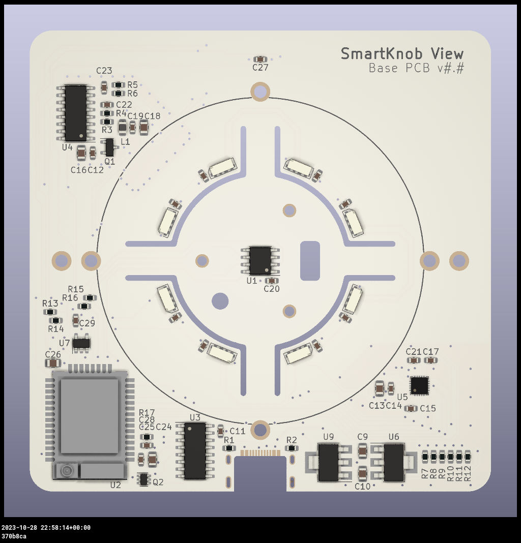
View the latest auto-generated (untested) Base PCB Interactive BOM and Screen PCB Interactive BOM (or, the combined BOM csv) for electronics/hardware parts list. โš ๏ธ These are auto-generated from the latest untested revision on GitHub. For tested/stable/recommended artifacts, use a release instead.

A few miscellaneous notes in the meantime:

  • There's limited space inside the LCD mount for wiring, and 8 wires need to fit through the hole in the center. I used 30 AWG wire-wrapping wire. Enamel-coated wire would probably work too.
  • Older versions of the design (as seen in the videos) used glued-on BF350-3AA strain gauges to detect presses; in v0.5 these were replaced with footprints for SMD resistors, which exhibit similar properties when stretched/compressed and are much easier to assemble.
  • The TMC6300 is tiny and has a bottom pad, so I would seriously consider getting a stencil along with the PCB order. Even with the stencil I needed to manually clean up some bridging afterward; I highly recommend Chip Quik NC191 gel flux, available on Amazon (or use this non-affiliate link instead) or from your electronics distributor of choice. Flux is also very helpful when soldering the LCD ribbon cable to to screen PCB.
  • For breadboard prototyping, the TMC6300-BOB or SparkFun's TMC6300 driver board are awesome and way easier to work with than the bare chip if you just want to play around with low current BLDC motors
  • For AliExpress purchases: I highly recommend only using AliExpress Standard Shipping (purchasing in the US). I have had multiple purchases take months or never get delivered when purchased with Cainiao or other low cost shipping options, whereas AliExpress Standard is very reliable and generally faster in my experience.
  • Make sure to check the open issues - this design is not yet "stable", so beware that everything may not go smoothly.

Future plans:

  • consider switch to using an ESP32-S3-MINI-1 module
  • get wifi configured and working (probably MQTT?). Currently memory is an issue with the full display framebuffer sprite. PSRAM might fix this (requires newer ESP-IDF & unreleased Arduino core, and from a brief test I got horrible performance with PSRAM enabled), or the next item might help reduce memory:
  • migrate to LVGL, for better display rendering and easy support for menus, etc. Shouldn't require a full 240x240x24b framebuffer in memory, freeing some for wifi, etc.
  • Home Assistant integration, or other real-world applications
  • ???
  • Profit ๐Ÿ˜‰

Already built one?

Check out the firmware/software documentation for tips on getting it programmed and hooking it up to your own software integrations.

If you've already uploaded the standard firmware and gone through the calibration process (see guide linked above if you don't know what this means), go to https://scottbez1.github.io/smartknob/ to try out an interactive web-based demo that uses Web Serial to talk to a SmartKnob that's plugged into your computer's USB port!

Base PCB

Ordering notes: use white soldermask, for reflecting light from RGB LED ring around the knob. Should be 1.2mm thick (not "standard" 1.6mm).

If you are ordering a stencil for solder paste from JLCPCB and plan to apply paste by hand (as shown in the video) without a stencil frame/machine, make sure to select "Customized size" and enter smaller dimensions (e.g. 100mm x 100mm) to avoid getting a much larger stencil than you need. This will also likely reduce the cost of shipping substantially! Also, select only the Top side; the bottom only has 2 SMT components - the motor connector and VEML7700 ALS - so it's not worth getting a stencil for that.

Latest auto-generated (untested and likely broken!) artifactsโš ๏ธ:

Schematic

Interactive BOM

PCB Packet

Gerbers

โš ๏ธ For tested/stable/recommended artifacts, use a release instead.

Screen PCB

Ordering notes: Must be 1.2mm thick (not "standard" 1.6mm) per mechanical design. (The PCB silkscreen mentions 0.6mm thickness - this is the thickness of the VHB tape for adhering the LCD; the PCB should be 1.2mm thick)

There are few enough components on the Screen PCB that I chose to hand-solder them rather than reflow with solder paste and a stencil, but if you order a stencil, see the note above about selecting a "Customized size" to be easier to handle and save on shipping. Also make sure to select the Bottom side only; all the components are on the bottom side of the screen PCB.

Latest auto-generated (untested and likely broken!) artifactsโš ๏ธ:

Schematic

Interactive BOM

PCB Packet

Gerbers

โš ๏ธ For tested/stable/recommended artifacts, use a release instead.

Printed parts

You will need six printed parts. The current stable designs can be found as STL assets in the v185 mechanical release or you can export the latest untested designs from the CAD model by opening it in Fusion 360: https://a360.co/3BzkU0n

The parts can probably be FDM 3D printed with a well-tuned printer, but the parts shown in videos/photos were MJF printed in nylon for tight tolerances and better surface finish.

If you wanted a simpler build, you could omit the LCD and just merge the knob + glass from the model into a single STL to get a closed-top knob.

Export and print the following 6 parts:

  • Enclosure
  • Knob (RotorAssembly->KnobAssembly->Knob)
  • ScreenPlatform
  • RotorSpacer (RotorAssembly->RotorSpacer)
  • MountBase
  • BackPlate

โš ๏ธ If you opt to go for MJF Nylon printing from JLCPCB, their system may complain about < 0.8mm wall thickness detected on the MountBase, ScreenPlatform and RotorSpacer parts. This appears to be a false positive, possibly on some of the print tapers. You should be able to ignore this, as all print orders at JLCPCB are subject to a final manual review, and they will contact you by email if there are any job-stopping issues or risks with your prints.

NanoFOC (3rd party)

If you're looking to tinker with FOC/haptic feedback, but don't want to build a full SmartKnob View yourself, I can recommend the NanoFOC DevKit++, an open-source design made and sold by a member of the SmartKnob community! It's super compact and is a great testbed or core for building your own BLDC-based haptic input device.

Image of the NanoFOC PCB

The NanoFOC uses an ESP32-S3, and the SmartKnob firmware works on it out of the box; just select the nanofoc environment in PlatformIO rather than the view environment when uploading.

Frequently Asked Questions (FAQ)

Can I use this cheap gimbal BLDC motor I found on AliExpress?

I can't stop you, but I will caution that you probably won't be super happy with it depending on your intended application.

Nearly every off-the-shelf BLDC gimbal motor that the community has tested (which is pretty much ALL the cheap ones you'll find on AliExpress, trust me) has moderate to severge cogging. That means the motor wants to snap to certain positions by itself even when unpowered. This means you won't be able to get completely smooth rotation when virtual detents are turned off, and the motor's cogging may interfere with or overpower the virtual detents, particularly if you set them to lower strength or make then very fine-grained.

The recommended motor is definitely the best (i.e. lowest cogging) off-the-shelf motor we've come across so far, and is the only readily-available motor that I would consider "good" for this application.

If you've found another motor that is completely smooth when unpowered, we'd LOVE to hear about it in the discord; if you're wondering about some cheap motor you saw online, either just order one and try it for yourself, or ask about it in discord but don't be surprised (or offended) if the response you get is something terse like "nope, no good".

How much does it cost?

I wish I could tell you now, but I don't actually know off the top of my head. Check back soon - I've only built a few so far, which was the result of a bunch of tinkering and prototyping over an extended period, so I don't have all the expenses tallied up yet. Probably less than $200 in parts? But some items have gotten more expensive, and you may be limited by minimum order quantities or shipping charges from multiple separate suppliers.

Does it work with XYZ?

Not yet, regardless of whatever "XYZ" you're thinking of. So far I've only implemented enough firmware for the demo shown in the video, so you can't actually use it for anything productive yet. The basic detent configuration API is there, but not much else. Lots of firmware work remains to be done. If you build one, I'd love your help adding support for "XYZ" though!

Can I buy one as a kit or already assembled?

Probably not? Or at least, I don't have any immediate plans to sell them myself. It's not that I don't want you to be happy, but hardware is a hard business and I just work on this stuff in my free time.

It's open source with a fairly permissive license though, so in theory anyone could start offering kits/assemblies. If someone does go down that route of selling them, note that attribution is required (and I wouldn't say no to royalties/tips/thanks if you're in a giving mood ๐Ÿ™‚).

Firmware and Software

More extensive documentation of the firmware and software (and how to get started) can be found in the dedicated SmartKnob Firmware and Software Guide

General Component Info

Magnetic encoders

MT6701 (MagnTek)

Excellent sensor at a reasonable price - highly recommended. Less noisy than TLV493D, and more responsive (control loop is more stable) using SSI.

  • Lots of IO options - SSI, I2C, and ABZ - should offer good response latency
  • SSI includes CRC to validate data
  • No power-down or low-power options - may not be ideal for battery-powered devices
  • Not available from US distributors (Mouser, Digi-Key)

Datasheet

Ordering (LCSC)

TLV493D (Infineon)

Not used in the SmartKnob view, but a common/popular magnetic encoder in general. It's a mediocre choice for a haptic feedback implementation. Easy to prototype with using Adafruit's QWIIC breakout board.

In my testing, it's noisy, requiring filtering/smoothing that can slow responsiveness, hurting control loop stability. Or, with less filtering, the noise can easily be "amplified" by the derivative component in the PID motor torque controller, causing audible (and tactile) humming/buzzing.

But the bigger issue is that there is apparently a known silicon issue that causes the internal ADC to sometimes completely lock up, requiring a full reset and re-configuration, which can cause delays/gaps in data! See section 5.6 in the User Manual

In the Master Controlled Mode (MCM) or the Fast Mode (FM) the ADC conversion may hang up. A hang up can
be detected by:
 - Frame Counter (FRM) counter stucks and does not increment anymore.

In my experience testing 4 different Adafruit breakout boards, 2 of them (50%) regularly exhibit this lockup behavior within a minute or two of use. It is possible to detect and auto-reset (and there is code in the project to do so), but it is slow and may cause undesirable jumps/delays if the sensor locks up often.

Datasheet

AS5600 (AMS)

A mediocre choice. Cheap breakout boards are readily available.

In my testing, it's fairly noisy (anecdotally, noisier than the TLV493d), requiring filtering/smoothing that can slow responsiveness, hurting control loop stability. Additionally, it saturates at a lower magnetic field strength than other sensors I tested, requiring a significant air gap (8-10mm) when used with a strong neodymium diametric magnet like Radial Magnets 8995.

Datasheet

Motor drivers

TMC6300-LA

This is a relatively new IC and it's a perfect match! There generally aren't any other drivers (with integrated fets) that meet the requirements for the low-voltage and low-current motors used in this project (DRV8316 might work, but has not been tested).

Highlights:

  • 2-11V DC motor supply input
  • Up to 1.2A RMS
  • Tiny (3x3mm QFN)

Datasheet

Product page

Motors

32mm Rotor, Hollow Shaft, Diametric magnet

  • 32mm rotor
  • 15mm overall height (including magnet), 12.75mm height w/o magnet, 9mm rotor height
  • low/zero cogging - excellent for completely smooth input
  • 5.9mm hollow shaft
  • built-in diametric magnet for encoder
  • Proven option

This is overall the easiest motor to get started with. Low cogging and a built-in diametric magnet are great!

Available from SparkFun!

Acknowledgements

This project was greatly inspired by Jesse Schoch's video "haptic textures and virtual detents" and the corresponding discussion in the SimpleFOC community. Seriously, this project wouldn't exist if not for that video - thank you Jesse!

License

This project is licensed under Apache v2 (software, electronics, documentation) and Creative Commons Attribution 4.0 (hardware/mechanical) (see LICENSE.txt and Creative Commons).

Copyright 2022 Scott Bezek

Licensed under the Apache License, Version 2.0 (the "License");
you may not use this file except in compliance with the License.
You may obtain a copy of the License at

    http://www.apache.org/licenses/LICENSE-2.0

Unless required by applicable law or agreed to in writing, software
distributed under the License is distributed on an "AS IS" BASIS,
WITHOUT WARRANTIES OR CONDITIONS OF ANY KIND, either express or implied.
See the License for the specific language governing permissions and
limitations under the License.

smartknob's People

Contributors

baku89 avatar brushknight avatar christophgysin avatar crosseyejack avatar jamessaporito avatar kagee avatar scottbez1 avatar vipqualitypost avatar

Stargazers

 avatar  avatar  avatar  avatar  avatar  avatar  avatar  avatar  avatar  avatar  avatar  avatar  avatar  avatar  avatar  avatar  avatar  avatar  avatar  avatar  avatar  avatar  avatar  avatar  avatar  avatar  avatar  avatar  avatar  avatar  avatar  avatar  avatar  avatar  avatar  avatar  avatar  avatar  avatar  avatar  avatar  avatar  avatar  avatar  avatar  avatar  avatar  avatar  avatar  avatar  avatar  avatar  avatar  avatar  avatar  avatar  avatar  avatar  avatar  avatar  avatar  avatar  avatar  avatar  avatar  avatar  avatar  avatar  avatar  avatar  avatar  avatar  avatar  avatar  avatar  avatar  avatar  avatar  avatar  avatar  avatar  avatar  avatar  avatar  avatar  avatar  avatar  avatar  avatar  avatar  avatar  avatar  avatar  avatar  avatar  avatar  avatar  avatar  avatar  avatar

Watchers

 avatar  avatar  avatar  avatar  avatar  avatar  avatar  avatar  avatar  avatar  avatar  avatar  avatar  avatar  avatar  avatar  avatar  avatar  avatar  avatar  avatar  avatar  avatar  avatar  avatar  avatar  avatar  avatar  avatar  avatar  avatar  avatar  avatar  avatar  avatar  avatar  avatar  avatar  avatar  avatar  avatar  avatar  avatar  avatar  avatar  avatar  avatar  avatar  avatar  avatar  avatar  avatar  avatar  avatar  avatar  avatar  avatar  avatar  avatar  avatar  avatar  avatar  avatar  avatar  avatar  avatar  avatar  avatar  avatar  avatar  avatar  avatar  avatar  avatar  avatar  avatar  avatar  avatar  avatar  avatar  avatar  avatar  avatar  avatar  avatar  avatar  avatar  avatar  avatar  avatar  avatar  avatar  avatar  avatar  avatar  avatar  avatar  avatar  avatar  avatar

smartknob's Issues

Is USB required to operate?

Would it be possible to also apply power from underneath, and not the USB-C port?

In a wall-mounted setup, having a USB plug sticking out would make it look dull. Instead, one could mount on top of a junction box within a wall, with a power supply underneath.

Add testpoints for LCD wires to top of screen PCB

Once the screen PCB is mounted to the motor mount base, and that is mounted to the base pcb, the screen's wires prevent the PCB from being lifted, so you can't easily access the wire solder points for probing.

It would be nice to have testpoints for all the screen wires on the top side of the PCB, so you can probe each one to determine which wire is which when soldering them to the base PCB.

Consider increasing diameter of screen PCB

To avoid LED light leakage around the LCD, it might make sense to increase the PCB's diameter. Might also be helpful to add silkscreen alignment marks on the top side to help with centering the LCD.

Need to make sure it's still narrow enough for the knob/rotor to slide past it during assembly.

Without screen PCB, how can I test features?

I didn't receive all components, no strain gauge at the moment, when I touch pins on strain gauge position, the mode is changed.


Please build project in debug configuration to get more details about an exception.
See https://docs.platformio.org/page/projectconf/build_configurations.html

--- Miniterm on COM3 115200,8,N,1 ---
--- Quit: Ctrl+C | Menu: Ctrl+T | Help: Ctrl+T followed by Ctrl+H ---
ets Jul 29 2019 12:21:46

rst:0x1 (POWERON_RESET),boot:0x13 (SPI_FAST_FLASH_BOOT)
configsip: 271414342, SPIWP:0xee
clk_drv:0x00,q_drv:0x00,d_drv:0x00,cs0_drv:0x00,hd_drv:0x00,wp_drv:0x00
mode:DIO, clock div:2
load:0x3fff0018,len:4
load:0x3fff001c,len:1044
load:0x40078000,len:10124
load:0x40080400,len:5828
entry 0x400806a8
use SENSOR_MT6701
MOT: Monitor enabled!
MOT: Init
MOT: Enable driver.
millilux: 165384.00
MOT: Align sensor.
MOT: Skip dir calib.
MOT: Skip offset calib.
millilux: 165470.39
MOT: No current sense.
MOT: Ready.
Press Y to run calibration
millilux: 165484.80
millilux: 165484.80
millilux: 165441.61
7.34
Got new config
millilux: 165441.61
millilux: 165441.61
millilux: 165441.61

5f08e6c80fe435ee6123ec589e5500f

Motor Specs

I think this project is really cool. I was hoping you could share detailed specs of the motor so we can find a suitable replacement that can potentially just drop right in.

Thanks,
Maxwell

Free up memory to enable wifi or bluetooth

Currently there is not enough memory available to initialize wifi (and I assume the same is likely true of bluetooth though I haven't tested yet).

A big culprit is the full 240x240x16b framebuffer in the display task which is used to avoid flickering when rendering. Two ideas of avoiding this memory issue:

  • potentially enable PSRAM (the ESP32-PICO-V3-02 has 2MB SPI PSRAM built in but not enabled by default in the current Arduino core). I did an initial test trying to enable PSRAM by using a newer arduino platform from git, but overall CPU performance ended up really bad. I didn't dig further where that performance hit was coming from, so I'm not sure if whether this approach is viable or not
  • migrate the graphics to LVGL, which supposedly can work with a smaller buffer and do tiled rendering (and do smarter rendering if regions haven't changed). I haven't used LVGL before, but it looks pretty powerful, and should also simplify adding things like a menu system later

There are some other memory issues, like the default arduino loop task allocates a (fixed) moderately sized stack but is essentially completely unused and gets deleted immediately after starting other tasks, but I think those issues are smaller scale compared to the framebuffer issue.

Create screen taping jig?

It's a little tricky to ensure the LCD is perfectly centered relative to the screen PCB (and therefore the rest of the mechanics and knob window) when permanently mounting it with VHB, so it might be nice to have a small 3d-printable jig to help with alignment.

It would hold the screen PCB (with alignment pin to ensure correct rotation) and have walls that align the LCD. Might be tricky since the LCD will be rotating down via its ribbon cable rather than simply translating straight down, but could be nice to get better overall alignment considering how permanent VHB is.

(If anyone tackles this, note that the existing LCD model in the F360 file is only a rough depiction based on a handful of dimensions from the datasheet. It would probably be best to put the LCD on a flatbed scanner to ensure dimensional accuracy)

Idea: make LEDs individually change colour/brightness in sync with rotation

Hello! Great project! Love the idea for model railway throttle controllers. (Plus so many more possibilities!)

I think it would be cool to sync the ring LED output to match the rotation of the knob, like a virtual indicator?

Could set a brightness or colour for general orientation point/direction, and mix the rest to blur/dim to background colour/darkness?

Cheers!
P.S. check out www.dcc-ex.com for open-source DIY model train control technology! ๐Ÿ˜Ž๐Ÿ‘

proto, handheld and handheld_tdisplay do not compile on master branch.

Currently on the master branch only the view target will compile.

Environment Status Duration


proto FAILED 00:00:04.469
view SUCCESS 00:00:43.869
handheld FAILED 00:00:07.100
handheld_tdisplay FAILED 00:00:06.988

The handheld and handheld mods seem to be a bit behind master, but do compile ok.

crash when run calibration with typing Y

--- Miniterm on COM6 115200,8,N,1 ---
--- Quit: Ctrl+C | Menu: Ctrl+T | Help: Ctrl+T followed by Ctrl+H ---
ets Jul 29 2019 12:21:46

rst:0x1 (POWERON_RESET),boot:0x13 (SPI_FAST_FLASH_BOOT)
configsip: 271414342, SPIWP:0xee
clk_drv:0x00,q_drv:0x00,d_drv:0x00,cs0_drv:0x00,hd_drv:0x00,wp_drv:0x00
mode:DIO, clock div:2
load:0x3fff0018,len:4
load:0x3fff001c,len:1044
load:0x40078000,len:10124
load:0x40080400,len:5828
entry 0x400806a8
Sprite created!
millilux: 26236.80
millilux: 26949.60
Press Y to run calibration
Ymillilux: 26942.40
millilux: 27057.60
millilux: 26697.60
millilux: 27021.60

Sensor measures positive for positive motor rotation: YES, Direction=CW
Guru Meditation Error: Core 1 panic'ed (Unhandled debug exception)
Debug exception reason: Stack canary watchpoint triggered (Motor)
Core 1 register dump:
PC : 0x400dfaf1 PS : 0x00060c36 A0 : 0x800e5255 A1 : 0x3ffb8280
A2 : 0x00000000 A3 : 0x00000011 A4 : 0x00000001 A5 : 0x3f404396
A6 : 0x3ffb8660 A7 : 0x00000008 A8 : 0x3f404385 A9 : 0x3ffb8474
A10 : 0x3ffb8290 A11 : 0x3ff9c510 A12 : 0x000000ff A13 : 0x0000ff00
A14 : 0x00ff0000 A15 : 0xff000000 SAR : 0x0000001d EXCCAUSE: 0x00000001
EXCVADDR: 0x00000000 LBEG : 0x400014fd LEND : 0x4000150d LCOUNT : 0xffffffff

ELF file SHA256: 0000000000000000

Backtrace: 0x400dfaf1:0x3ffb8280 0x400e5252:0x3ffb8590 0x400e528a:0x3ffb8620 0x400da4ca:0x3ffb8660 0x400d3280:0x3ffb8700 0x400d2ced:0x3ffb8850 0x400883f2:0x3ffb8870
#0 0x400dfaf1:0x3ffb8280 in _svfprintf_r at /Users/ivan/e/newlib_xtensa-2.2.0-bin/newlib_xtensa-2.2.0/xtensa-esp32-elf/newlib/libc/stdio/../../../.././newlib/libc/stdio/vfprintf.c:929
#1 0x400e5252:0x3ffb8590 in _vsnprintf_r at /Users/ivan/e/newlib_xtensa-2.2.0-bin/newlib_xtensa-2.2.0/xtensa-esp32-elf/newlib/libc/stdio/../../../.././newlib/libc/stdio/vsnprintf.c:72
#2 0x400e528a:0x3ffb8620 in vsnprintf at /Users/ivan/e/newlib_xtensa-2.2.0-bin/newlib_xtensa-2.2.0/xtensa-esp32-elf/newlib

Idea: The BLDC motor could be used to implement inertial scrolling

Imagine a scroll wheel that had the inertial scrolling commonly seen on multi-touch trackpads. But because the motion could be physically represented by the driven motor, the software could adapt to the user. The user could have dents until they fling it. The fling could have friction that lessens if the user give additional flings upon slowing.

Note: This is constitutes Prior Art. The feature described is currently in development and offered freely to the public domain and may not be used in patents.

Screen PCB thickness

First of all thanks for open-sourcing this awesome design! I just noticed that the readme states the screen PCB must be 1.2mm thick ("Ordering notes: Must be 1.2mm thick (not "standard" 1.6mm) per mechanical design.") but on the silkscreen of the PCB there's a big "0.6mm thick" label. Probably just a small copy and paste mistake from the ordering notes of the base PCB, thought I'd mention it anyway.

PS: Can't wait for my PCB and parts to arrive and build one up. :-)

Integrate with ESPHome

A quick suggestion: ESPHome is an exceptionally well though-out modular environment where most of the work has been done in terms of integration with many third party systems. If you would develop your I/O as an ESPHome component, you could save tons of work and concentrate on your special features supported by the hardware.

Also have a peak at OpenHASP on how LVGL is approached. It hardly relies on touch functionality, though, so may not be appropriate here.

Refactor detent configuration for more flexibility

The current detent configuration is pretty flexible (number of detents, size of detents, strength, etc), but isn't the only kind of haptic feedback you might want to provide.

Idea is to extract a lot of the existing detent-specific code into a DetentEngine implementation of a more general (and swappable) HapticEngine interface. The HapticEngine interface would mostly just take the current mechanical angle as input and return a torque value as output.

Other implementations might be a jog/shuttle engine which might have stops placed for 1x, 2x, 10x playback rates in either direction, or an inertial smooth scroll engine (it remains to be seen if this can be implemented well with the current control system).

openinput

Thinking of integrating something like this in our input device firmware project openinput
Can think of couple applications for this like keyboards, and mouse scroll wheel, and stand alone ofcourse

That said the way it currently is wont integrate well (arduino and esp), so I will have to do something from scratch.

Yet I think it would be nice to integrate here the openinput-protocol for configurations and interactions, the protocol is under development, so feel free to suggest functions that would be useful for this so that they can be thought about and integrated

Great job!

Sorry, this is not an issue at all. I just wanted to say excellent work! This is a very creative project. You basically made a force feedback steering wheel. I'm a developer at iRacing.com, if your ever curious about making it work with DirectInput let me know. And if you ever get it to a commercial state I would love to add it into our video game, our members would be ecstatic to have something like this to make brake bias adjustments.

LICENSE.txt lacking Copyright Year and Owner

Hey, just an FYI:

To apply the Apache License to your work, attach the following
boilerplate notice, with the fields enclosed by brackets "{}"
replaced with your own identifying information. (Don't include
the brackets!) The text should be enclosed in the appropriate
comment syntax for the file format. We also recommend that a
file or class name and description of purpose be included on the
same "printed page" as the copyright notice for easier
identification within third-party archives.

Copyright {yyyy} {name of copyright owner}

@scottbez1 protect your IP! This project is amazing!

Move hardcoded configurations to a file on filesystem

There are a number of hardcoded configuration values currently:

  • electrical zero angle (motor + sensor alignment)
  • motor pole count
  • motor orientation
  • HX711 upper and lower thresholds
  • VEML7700 lux mapping to LED/backlight brightness

Might be nice to move these to a file (json?) on spiffs/littlefs, and ideally eventually add a calibration menu that can write/update that file automatically.

How much power does this consume?

I wonder how much power this uses and whether it would be feasible for battery-powered or low-power products. Presumably the consumption differs based on usage (artificial detents, no motor usage etc.)

TMC6300 is so hot after soldered

@scottbez1 Hi Scott, I soldered all most components on base PCB, when connected PCB board with PC, it looks good from PlatformIO monitor from VSCode, but TMC6300 is so hot, do you know which component is short or some other reasons?

base1

base2

Idea: ethernet/PoE

Is there any plan to have a version supporting wired Ethernet connetion?

ESP32 can accomodate with various Ethernet PHY chips, also combined with an 802.3af PoE supply this project could really kick ass in the home automation world. Think of this also as mounted on wall on the end of a CAT5 cable supplying both data and power...

Add alignment pins to back plate?

Next to the left/right mounting holes where there is room, add pins and matching PCB holes for help aligning the base PCB with the back plate when mounting it.

Use FSR instead of Strain Gauge

Hi there,

as you've mentioned multiple times in the readme, working with strain gauges isn't trivial, so it's easy to screw up when mounting them to the PCB. You can practice mounting them somewhere else beforehand of course, but that means ordering more units than you'd actually need.

I'm currently working on a project where I also need to detect pressure being applied to something, and I've found that Force-Sensitive Resistors (FSRs) are quite easy to work with and offer a straight-forward implementation when it comes to measuring force.
Here's an example of what I'm talking about
They usually are a bit more expensive, but as I mentioned, working with them is probably easier than using strain gauges.

Maybe give them a try? :)

The board restarts indefinitely

LOG:

Executing task in folder test: C:\Users\wlj.platformio\penv\Scripts\platformio.exe run --target upload --target monitor <

Processing view (board: esp32doit-devkit-v1; platform: [email protected]; framework: arduino)

Verbose mode can be enabled via -v, --verbose option
CONFIGURATION: https://docs.platformio.org/page/boards/espressif32/esp32doit-devkit-v1.html
PLATFORM: Espressif 32 (3.4.0) > DOIT ESP32 DEVKIT V1
HARDWARE: ESP32 240MHz, 320KB RAM, 4MB Flash
DEBUG: Current (esp-prog) External (esp-prog, iot-bus-jtag, jlink, minimodule, olimex-arm-usb-ocd, olimex-arm-usb-ocd-h, olimex-arm-usb-tiny-h, olimex-jtag-tiny, tumpa)
PACKAGES:

  • framework-arduinoespressif32 3.10006.210326 (1.0.6)
  • tool-esptoolpy 1.30100.210531 (3.1.0)
  • tool-mkspiffs 2.230.0 (2.30)
  • toolchain-xtensa32 2.50200.97 (5.2.0)
    LDF: Library Dependency Finder -> https://bit.ly/configure-pio-ldf
    LDF Modes: Finder ~ chain, Compatibility ~ soft
    Found 37 compatible libraries
    Scanning dependencies...
    Dependency Graph
    |-- 2.2.0
    | |-- 1.0
    | |-- 1.0.1
    |-- 1.0.3
    | |-- 1.0.1
    |-- 1.9.1
    |-- <TFT_eSPI> 2.4.25
    | |-- 1.0
    | | |-- 1.0
    | |-- 1.0
    | |-- 1.0
    |-- 3.5.0
    | |-- 1.0
    |-- 0.7.5
    |-- 1.1.1
    | |-- 1.11.3
    | | |-- 1.0.1
    | | |-- 1.0
    | |-- 1.0.1
    | |-- 1.0
    Building in release mode
    Retrieving maximum program size .pio\build\view\firmware.elf
    Checking size .pio\build\view\firmware.elf
    Advanced Memory Usage is available via "PlatformIO Home > Project Inspect"
    RAM: [= ] 5.4% (used 17648 bytes from 327680 bytes)
    Flash: [=== ] 27.3% (used 357434 bytes from 1310720 bytes)
    Configuring upload protocol...
    AVAILABLE: esp-prog, espota, esptool, iot-bus-jtag, jlink, minimodule, olimex-arm-usb-ocd, olimex-arm-usb-ocd-h, olimex-arm-usb-tiny-h, olimex-jtag-tiny, tumpa
    CURRENT: upload_protocol = esptool
    Looking for upload port...
    Auto-detected: COM6
    Uploading .pio\build\view\firmware.bin
    esptool.py v3.1
    Serial port COM6
    Connecting......
    Chip is ESP32-PICO-D4 (revision 1)
    Features: WiFi, BT, Dual Core, 240MHz, Embedded Flash, VRef calibration in efuse, Coding Scheme None
    Crystal is 40MHz
    MAC: 4c:75:25:a8:34:50
    Uploading stub...
    Running stub...
    Stub running...
    Changing baud rate to 460800
    Changed.
    Configuring flash size...
    Auto-detected Flash size: 4MB
    Flash will be erased from 0x00001000 to 0x00005fff...
    Flash will be erased from 0x00008000 to 0x00008fff...
    Flash will be erased from 0x0000e000 to 0x0000ffff...
    Flash will be erased from 0x00010000 to 0x00067fff...
    Compressed 17104 bytes to 11191...
    Writing at 0x00001000... (100 %)
    Wrote 17104 bytes (11191 compressed) at 0x00001000 in 0.5 seconds (effective 265.5 kbit/s)...
    Hash of data verified.
    Compressed 3072 bytes to 128...
    Writing at 0x00008000... (100 %)
    Wrote 3072 bytes (128 compressed) at 0x00008000 in 0.1 seconds (effective 428.9 kbit/s)...
    Hash of data verified.
    Compressed 8192 bytes to 47...
    Writing at 0x0000e000... (100 %)
    Wrote 8192 bytes (47 compressed) at 0x0000e000 in 0.1 seconds (effective 664.2 kbit/s)...
    Hash of data verified.
    Compressed 357536 bytes to 190478...
    Writing at 0x00010000... (8 %)
    Writing at 0x00018fa4... (16 %)
    Writing at 0x0002ae4c... (25 %)
    Writing at 0x00031fba... (33 %)
    Writing at 0x00037609... (41 %)
    Writing at 0x0003ce26... (50 %)
    Writing at 0x00043401... (58 %)
    Writing at 0x0004bfda... (66 %)
    Writing at 0x0005193c... (75 %)
    Writing at 0x000579b5... (83 %)
    Writing at 0x0005d835... (91 %)
    Writing at 0x000635f9... (100 %)
    Wrote 357536 bytes (190478 compressed) at 0x00010000 in 4.7 seconds (effective 608.0 kbit/s)...
    Hash of data verified.

Leaving...
Hard resetting via RTS pin...
=========================================== [SUCCESS] Took 15.55 seconds ===========================================
--- Available filters and text transformations: colorize, debug, default, direct, esp32_exception_decoder, hexlify, log2file, nocontrol, printable, send_on_enter, time
--- More details at https://bit.ly/pio-monitor-filters

Please build project in debug configuration to get more details about an exception.
See https://docs.platformio.org/page/projectconf/build_configurations.html

--- Miniterm on COM6 115200,8,N,1 ---
--- Quit: Ctrl+C | Menu: Ctrl+T | Help: Ctrl+T followed by Ctrl+H ---
ets Jun 8 2016 00:22:57

rst:0x1 (POWERON_RESET),boot:0x13 (SPI_FAST_FLASH_BOOT)
configsip: 188777542, SPIWP:0xee
clk_drv:0x00,q_drv:0x00,d_drv:0x00,cs0_drv:0x00,hd_drv:0x00,wp_drv:0x00
mode:DIO, clock div:2
load:0x3fff0018,len:4
load:0x3fff001c,len:1044
load:0x40078000,len:10124
load:0x40080400,len:5828
entry 0x400806a8
Guru Meditation Error: Core 1 panic'ed (IllegalInstruction). Exception was unhandled.
Memory dump at 0x400f2040: ffff5755 ffffffff ffffffff
Core 1 register dump:
PC : 0x400f2044 PS : 0x00060230 A0 : 0x0000000d A1 : 0x3ffb8660
A2 : 0x00000021 A3 : 0x00000000 A4 : 0x0000001a A5 : 0x3ff49028
A6 : 0x0000001a A7 : 0x00000001 A8 : 0x00002a00 A9 : 0x00000a00
A10 : 0x0000000a A11 : 0x3ff000c4 A12 : 0x06ff1f78 A13 : 0x3ffb1f60
A14 : 0x3ffb8058 A15 : 0x00000001 SAR : 0x0000000e EXCCAUSE: 0x00000000
EXCVADDR: 0x00000000 LBEG : 0x00000000 LEND : 0x00000000 LCOUNT : 0x00000000

ELF file SHA256: 0000000000000000

Backtrace: 0x400f2044:0x3ffb8660 0x0000000a:0x3ffb8690 0x400d5f67:0x3ffb86d0 0x400d3118:0x3ffb8700 0x400d2ced:0x3ffb8850 0x400883f2:0x3ffb8870
#0 0x400f2044:0x3ffb8660 in mcpwm_gpio_init at /home/runner/work/esp32-arduino-lib-builder/esp32-arduino-lib-builder/esp-idf/components/driver/mcpwm.c:699
#1 0x0000000a:0x3ffb8690 in ?? ??:0
#2 0x400d5f67:0x3ffb86d0 in BLDCDriver6PWM::init() at .pio/libdeps/view/Simple [email protected]/src/drivers/BLDCDriver6PWM.cpp:61
#3 0x400d3118:0x3ffb8700 in MotorTask::run() at src/motor_task.cpp:61
#4 0x400d2ced:0x3ffb8850 in Task::taskFunction(void*) at src/task.h:46
#5 0x400883f2:0x3ffb8870 in vPortTaskWrapper at /home/runner/work/esp32-arduino-lib-builder/esp32-arduino-lib-builder/esp-idf/components/freertos/port.c:355 (discriminator 1)

Rebooting...
ets Jun 8 2016 00:22:57

rst:0xc (SW_CPU_RESET),boot:0x13 (SPI_FAST_FLASH_BOOT)
configsip: 188777542, SPIWP:0xee
clk_drv:0x00,q_drv:0x00,d_drv:0x00,cs0_drv:0x00,hd_drv:0x00,wp_drv:0x00
mode:DIO, clock div:2
load:0x3fff0018,len:4
load:0xffffffff,len:-1
ets Jun 8 2016 00:22:57

rst:0x10 (RTCWDT_RTC_RESET),boot:0x13 (SPI_FAST_FLASH_BOOT)
configsip: 188777542, SPIWP:0xee
clk_drv:0x00,q_drv:0x00,d_drv:0x00,cs0_drv:0x00,hd_drv:0x00,wp_drv:0x00
mode:DIO, clock div:2
load:0x3fff0018,len:4
load:0x3fff001c,len:1044
load:0x40078000,len:10124
load:0x40080400,len:5828
entry 0x400806a8
Guru Meditation Error: Core 1 panic'ed (IllegalInstruction). Exception was unhandled.
Memory dump at 0x400f2040: ffff5755 ffffffff ffffffff
Core 1 register dump:
PC : 0x400f2044 PS : 0x00060230 A0 : 0x0000000d A1 : 0x3ffb8660
A2 : 0x00000021 A3 : 0x00000000 A4 : 0x0000001a A5 : 0x3ff49028
A6 : 0x0000001a A7 : 0x00000001 A8 : 0x00002a00 A9 : 0x00000a00
A10 : 0x0000000a A11 : 0x3ff000c4 A12 : 0x06ff1f78 A13 : 0x3ffb1f60
A14 : 0x3ffb8058 A15 : 0x00000001 SAR : 0x0000000e EXCCAUSE: 0x00000000
EXCVADDR: 0x00000000 LBEG : 0x00000000 LEND : 0x00000000 LCOUNT : 0x00000000

ELF file SHA256: 0000000000000000

Backtrace: 0x400f2044:0x3ffb8660 0x0000000a:0x3ffb8690 0x400d5f67:0x3ffb86d0 0x400d3118:0x3ffb8700 0x400d2ced:0x3ffb8850 0x400883f2:0x3ffb8870
#0 0x400f2044:0x3ffb8660 in mcpwm_gpio_init at /home/runner/work/esp32-arduino-lib-builder/esp32-arduino-lib-builder/esp-idf/components/driver/mcpwm.c:699
#1 0x0000000a:0x3ffb8690 in ?? ??:0
#2 0x400d5f67:0x3ffb86d0 in BLDCDriver6PWM::init() at .pio/libdeps/view/Simple [email protected]/src/drivers/BLDCDriver6PWM.cpp:61
#3 0x400d3118:0x3ffb8700 in MotorTask::run() at src/motor_task.cpp:61
#4 0x400d2ced:0x3ffb8850 in Task::taskFunction(void*) at src/task.h:46
#5 0x400883f2:0x3ffb8870 in vPortTaskWrapper at /home/runner/work/esp32-arduino-lib-builder/esp32-arduino-lib-builder/esp-idf/components/freertos/port.c:355 (discriminator 1)

Rebooting...
ets Jun 8 2016 00:22:57

How to solder strain gauges?

Quick question only sort of related to your project - how did you solder the strain gauges? I bought some of a similar kind a while ago for a different project but I couldn't figure out how to reliably connect to the pads on the gauge without destroying it.

32ย mm BLDC Motor isn't for sale anymore :(

Hello, I saw your video yesterday for the first time and was blown away. I always wanted such a thing, but DIY and not like the Nest thing. I directly made a shopping list for all parts and had no problem to find all the parts besides the BLDC Motor. And also the price for all parts with shipping to Germany is around โ‚ฌ85, pretty good. And if the shipping cost for the PCBs weren't that high, it would be even cheaper.

Likewise, I first used the link to find the motor isn't for sale anymore. So I thought maybe find it somewhere else on the internet, but... google pictures said No. I really tried to find the thing with all the product pictures the names of the specifications, but I didn't find it. The only seller for the motor in my opinion was AliExpress. I couldn't find another platform where you could buy this exact motor.

The only motor of similar size I could spot was a bit bigger one

I could use the smaller motor, but you said on your other branch "moderate cogging - not ideal for completely smooth input". I ordered this one, but do you think it is relatively easy to remodel the design for the 34ย mm Version? Or is there definitely not enough space, so I had to remodel the complete exterior covering?
Maybe you found a better motor till now.

Happy to hear from you ๐Ÿ‘

Current draw

Hi! Thanks for open sourcing this project. Looks amazing! I am looking into integrate this into my hobby IoT project. I am curious what the current consumption. My IoT project takes in power through usb 2.0, so in total 500 mA.

Brushless driver

With which integrated could I replace TMC6300-LA but which one can I find on Aliexpress? (DRV8316 is still not on Aliexpress)

Idea: Add ethernet port with Poe support

I think adding support for ethernet with poe can help in cases where latency is important, it also makes power distribution easier.

It may not be convenient in all cases, therefore I propose to create two versions, the normal one and the one with ethernet and poe support.

Motor out of stock

Not a major issue as you've said you've got several others on the way for testing, but the link to the motor you used is now out of stock: AliExpress

Idea: The BLDC motor could greatly improve upon the 3D/XYZ-YPR mouse

There are many projects that try to mechanically present an interface for users to input XYZ movement and Yaw Pitch Roll for interaction with models in 3D space. The use of BLDC motors in addition to or in place of potentiometers, rotary encoders, and similar electro-mechanical sensors could greatly improve the user experience ans simplify the mechanical design. Rather than having to find a mechanical device that was designed for the way the user intuitively wants to give input, the user could purchase a device that fits a much larger market and customize it through software to deliver the experience that allows each user to stay in flow and not be distracted by the hardware interface.

Note: This is constitutes Prior Art. The feature described is currently in development and offered freely to the public domain and may not be used in patents.

How to check whether HX711/Strain gauges has problem?

It's not working on my side, before fixed strain gauges on PCB, I just want to validate strain gauges is originally working with HX711.

There's current on 6 pads for strain gauges, but no response(the screen keeps showing Unbounded No detents which is the mode by defaut) when I touched 4 strain gauges when powered.

image

Suggestion: Save money in your BOM and use cheap linear hall effect sensors instead of the MT6701-CT

I had a look at your design (which is fantastic!) and I couldn't help but notice you're using the MT6701-CT for positional encoding. Let me first state: That's fine. The MT6701-CT is a fantastic chip but it has two issues:

  • It's expensive (like $2/each in bulk)
  • It requires a relatively expensive ($0.25/each) diametrically-magnetized disc magnets that are kind of hard for every day people to source.

For my Void Switch keyboards (https://github.com/riskable/void_switch) I came up with an analog rotary encoder design (well, several of them actually) that utilizes just two super cheap ($0.09/each) GH39FKSW (or OH49E-S) linear hall effect sensors with ultra cheap ($0.01/each) 4x2mm (or 4x1mm) magnets to perform the same exact job as a single MT6701-CT.

Here's a screenshot of what the simplest version looks like:

Analog Hall Effect Rotary Encoder PCB Screenshot

The little white circles represent the location of the magnets. They're alternating N/S and since the sensors are analog the resolution is configurable just like the detents/tactile feedback you've come up with for your smart knob. The rest of it should be pretty self-explanatory but I can provide intimate details if you want (including the conditional "truth table" that determines knob direction/motion).

The only downside to this method is it requires 6 magnets (or as many as you want if you desire a bigger ring; just make it an even number--my Riskeyboard 70 I'm typing on uses a ring of 12) instead of just one like with the MT6701-CT.

There's also a way you can do away with your strain gauges (though that's super clever I love it) to add a pushbutton feature by simply adding a 3rd hall effect sensor in the middle and using a mechanical setup like so:

https://gfycat.com/fabulouscostlyblackrhino

Anyway, this is totally not important. Just a way to save a couple bucks per PCB.

How does the magnetic encoder work?

This a an amazing work both in enginering and designing. I really apperiate it.
But there is one thing I couldn't understand. MountBase is covering the MT6701 sensor. Both are stationary. And I didn't see any magnet using in the CAD file. I could not figure out what magnet feild the MT6701 is sensing. Maybe there is a donut shaped magnet attached to the rotor? Could you please explain it a littele bit? Maybe in your next video. Thanks in advance.

Remove service loop silkscreen from screen PCB

It's essentially impossible to align all the 30AWG wires into a service loop without overlapping, so if you actually follow the indicated silkscreen marks you'll end up with overlapping wires that are taller than the extra thin VHB tape. I found it worked better to just skip the service loops (which I don't think were usable anyway due to the tight clearances).

Pick & Place File

Would it be possible to include a simple pick & place file in addition to the bom?
I'm not that experienced with smd soldering and would like to order the pcbs already assembled at factory, at least for the general stuff like resistors and capacitors.

can't find ESP32 when upload firmware to base board.

Building in release mode
Retrieving maximum program size .pio\build\view\firmware.elf
Checking size .pio\build\view\firmware.elf
Advanced Memory Usage is available via "PlatformIO Home > Project Inspect"
RAM: [= ] 5.4% (used 17648 bytes from 327680 bytes)
Flash: [=== ] 27.3% (used 357450 bytes from 1310720 bytes)
Configuring upload protocol...
AVAILABLE: esp-prog, espota, esptool, iot-bus-jtag, jlink, minimodule, olimex-arm-usb-ocd, olimex-arm-usb-ocd-h, olimex-arm-usb-tiny-h, olimex-jtag-tiny, tumpa
CURRENT: upload_protocol = esptool
Looking for upload port...
Auto-detected: COM3
Uploading .pio\build\view\firmware.bin
esptool.py v3.1
Serial port COM3
Connecting......................................_____

A fatal error occurred: Failed to connect to ESP32: Timed out waiting for packet header
*** [upload] Error 2
================================================================================================================================ [FAILED] Took 28.07 seconds ================================================================================================================================
Environment Status Duration


view FAILED 00:00:28.074
=========================================================================================================================== 1 failed, 0 succeeded in 00:00:28.074 ===========================================================================================================================The terminal process "C:\Users\zinwa.platformio\penv\Scripts\platformio.exe 'run', '--target', 'upload', '--environment', 'view'" terminated with exit code: 1.

Terminal will be reused by tasks, press any key to close it.

ae60cb1796eccbd3c3ea62f307c444d

Idea: Momentum scrolling

Much like some logitech scroll wheels implementing a long running scroll with the motor kicked off by initial user interaction would feel lovely on this project. Seeing it decelerate on the display too would feel soo nice.

Increase vertical clearance between LCD and knob

Could use another ~0.5mm between LCD and the inside/inner-bottom face of the knob, to account for assembly imperfections, to ensure the knob doesn't scrape on the screen.

It should be ok to decrease the vertical clearance below the screen pcb correspondingly; there's more clearance here than necessary.

Change R3 to 10k

Per HX711 datasheet: (R1 in datasheet is R3 on view base, R2 in datasheet is R4 on view base)
V AVDD =V BG *(R1+R2)/R2

So with R1(aka R3)=20k, this comes out to 1.25V*(20k+8.2k)/8.2k = 4.3V which is higher than VSUP (3.3V).

Changing R1(aka R3) to 10k, we get 1.25V*(10k+8.2k)/8.2k = 2.77V which fulfills 2.6-5.5V range, and is a "minimum of
100mV below VSUP voltage" as recommended by the datasheet.

This should make the analog voltage supply more resilient to noise on the 3.3V rail.

Debug exception reason: Stack canary watchpoint triggered (Motor)

Hi,

First thanks a lot for this amazing piece of DIY. Great to get a hands on feeling of haptic feedback.
I am having a little trouble flashing the firmware and getting it to work. First, on the master branch only the view env compiles (which I believe is normal looking at the dependencies). After flashing the view build I get stuck in the following bootloop :

`ets Jul 29 2019 12:21:46

rst:0x1 (POWERON_RESET),boot:0x13 (SPI_FAST_FLASH_BOOT)
configsip: 271414342, SPIWP:0xee
clk_drv:0x00,q_drv:0x00,d_drv:0x00,cs0_drv:0x00,hd_drv:0x00,wp_drv:0x00
mode:DIO, clock div:2
load:0x3fff0018,len:4
load:0x3fff001c,len:1044
load:0x40078000,len:10124
load:0x40080400,len:5828
entry 0x400806a8
Sprite created!
millilux: 1764.00
Guru Meditation Error: Core 1 panic'ed (Unhandled debug exception)
Debug exception reason: Stack canary watchpoint triggered (Motor)
Core 1 register dump:
PC : 0x400dfa22 PS : 0x00060836 A0 : 0x800e51e5 A1 : 0x3ffb8220
A2 : 0x00000000 A3 : 0x3ffb8414 A4 : 0x00000000 A5 : 0x00000000
A6 : 0x3ffb8600 A7 : 0x00000008 A8 : 0x3ffb8530 A9 : 0x3ffb8210
A10 : 0x3ffb8230 A11 : 0x3ff9c510 A12 : 0x000000ff A13 : 0x0000ff00
A14 : 0x00ff0000 A15 : 0xff000000 SAR : 0x00000020 EXCCAUSE: 0x00000001
EXCVADDR: 0x00000000 LBEG : 0x400014fd LEND : 0x4000150d LCOUNT : 0xffffffff

ELF file SHA256: 0000000000000000

Backtrace: 0x400dfa22:0x3ffb8220 0x400e51e2:0x3ffb8530 0x400e521a:0x3ffb85c0 0x400da45a:0x3ffb8600 0x400d3cfb:0x3ffb86a0 0x400d5218:0x3ffb86d0 0x400d3152:0x3ffb8700 0x400d2cdd:0x3ffb8850 0x400883f2:0x3ffb8870

Rebooting...
`

Should I assume bad soldering on the TMC6300 ? Is there something else I am missing ?

Thanks a lot

Recommend Projects

  • React photo React

    A declarative, efficient, and flexible JavaScript library for building user interfaces.

  • Vue.js photo Vue.js

    ๐Ÿ–– Vue.js is a progressive, incrementally-adoptable JavaScript framework for building UI on the web.

  • Typescript photo Typescript

    TypeScript is a superset of JavaScript that compiles to clean JavaScript output.

  • TensorFlow photo TensorFlow

    An Open Source Machine Learning Framework for Everyone

  • Django photo Django

    The Web framework for perfectionists with deadlines.

  • D3 photo D3

    Bring data to life with SVG, Canvas and HTML. ๐Ÿ“Š๐Ÿ“ˆ๐ŸŽ‰

Recommend Topics

  • javascript

    JavaScript (JS) is a lightweight interpreted programming language with first-class functions.

  • web

    Some thing interesting about web. New door for the world.

  • server

    A server is a program made to process requests and deliver data to clients.

  • Machine learning

    Machine learning is a way of modeling and interpreting data that allows a piece of software to respond intelligently.

  • Game

    Some thing interesting about game, make everyone happy.

Recommend Org

  • Facebook photo Facebook

    We are working to build community through open source technology. NB: members must have two-factor auth.

  • Microsoft photo Microsoft

    Open source projects and samples from Microsoft.

  • Google photo Google

    Google โค๏ธ Open Source for everyone.

  • D3 photo D3

    Data-Driven Documents codes.