a raspberry pi project to capture readings from a power meter
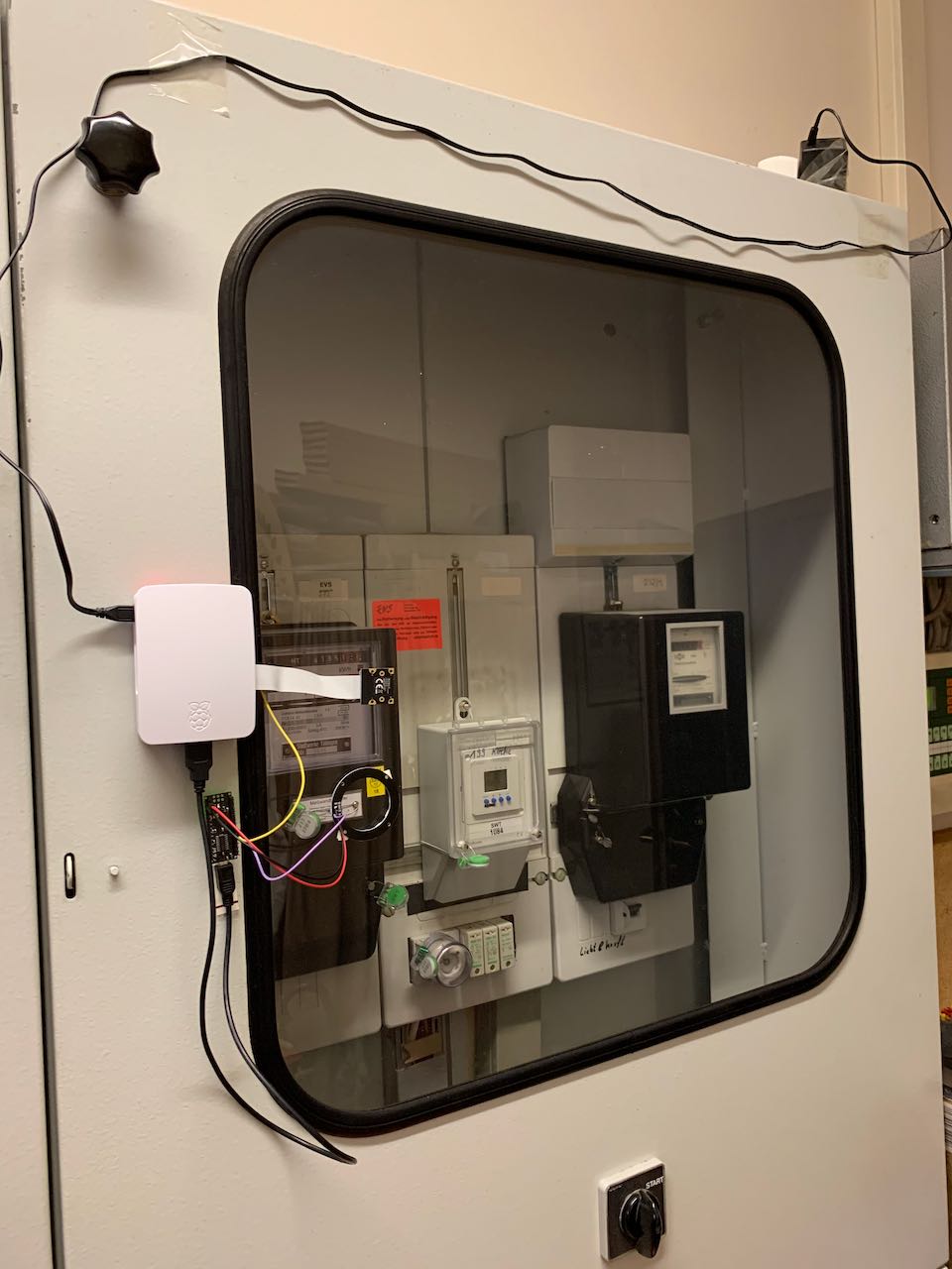
This is how it looks:
And this is what it produces:

Since I did not have time to wait 6 weeks for delivery from China, I sourced the parts from german suppliers. I assume that the price of at least some of the components would have been much cheaper if I had ordered at aliexpress...
- Raspberry Pi 3, Model B, 1 GB RAM (34 €)
- Raspberry Pi power supply 5V 2.5A (7 €)
- Raspberry Pi Camera RPI JT CAM 5MP from Joy-IT (10,64 €)
- Raspberry Pi case (5,34 €)
- Micro SD 16 GB (7,70 €) - I ordered this one but actuall received a 32GB SD card...
- AZDelivery 5V RGB LED Ring WS2812B 12-Bit 50mm Arduino (3 pieces, together for 7,99€)
- Arduino Nano, USB cable and 3 Dupont wires (still had it lying around, 1-2 Euros at aliexpress)
The location of the power meter has access to electric power, but no other infrastructure is available (especially no WLAN). It is also not located inside my house, but inside a locked room in a public building (the local church). The room has a small window to the north, so it is very poorly lit.
The powerpi is equipped with a camera module. The power meter itself is located inside a fuse box that has a transparent door. So I glued the powerpi to the outside of the fuse box, with the camera located about 10 centimeters away from the meter.
The idea is that the powerpi takes fotos in regular intervals. Since there is no stationary WLAN available, I will regularly drive by and collect the readings by opening a WLAN from my cell phone.
- In its first stage, the powerpi will just take fotos regularly. I will collect the fotos and extract the readings manually
- In the second stage, it could extract the readings automatically using OCR.
There are a number of issues to be solved:
I configured the powerpi to automatically connect to my IPhone's WLAN access point as soon as I opened it.
To do this, I added the following lines to /etc/wpa_supplicant/wpa_supplicant.conf:
network={
	ssid="iPhone von Philipp"
	psk="<zip>"
	key_mgmt=WPA-PSK
}
Unfortunately, this only works when a screen is connected via HDMI. Not sure why. I discovered that execution of a WLAN scan after reboot fixed the issue:
sudo iwlist wlan0 scan
My testing showed that it is enough to execute the command once after reboot, but I wanted to make sure that it still works if I return to the powerpi after several weeks. Therefore I scheduled the scan to be executed every 10 minutes using crontab.
In addition, I edited /etc/network/interfaces and added the following lines:
interface wlan0
request 172.20.10.9
This should make sure the powerpi always has the same IP address.
My on site testing showed that I am able to access the powerpi without actually entering the locked room. In fact, I don't even need to enter the building itself. I can open my access point outside and collect the readings from there.
See the folder /scripts_laptop for the scripts I use on my laptop to access the powerpi.
I added my public key to the ~/.ssh/authorized_keys file so that I don't have to type my password every time.
This one is easy.
The command to take a foto is raspistill.
The camera needs to be enabled using raspi-config first, but after that, no surprises at all.
I created a script located in /scripts_powerpi to take the foto and scheduled it to run at the top of every hour using crontab.
For the beginning, the cron expression is 0 * * * *.
Foto size is about 200k at a resolution of 640*480, which seems like a reasonable size when buffering it for 2-3 weeks.
Since the powerpi is relying on daylight coming through a north-facing window, I did not expect to get too many good fotos at all. In fact, during the first few days, none was usable. Therefore, I bought an LED ring with 12 LEDs which I glued below the camera.
It should be possible to use GPIO to switch the LED ring on right before taking the foto and switch it off again afterwards. I found a blog describing how to do it: http://frederickvandenbosch.be/?p=1014
Unfortunately, I was not able to get this running. The LED ring reacted completely random, if at all. I suspect the 3.3V logic level of the raspberry pi to be the reason, but it might just be my incopetence - I will give it a try again at a later point in time.
For now, I found an alternative solution that worked right out of the box.
I used an Arduino Nano (I have plenty of those lying around, they cost around 1-2 Dollars at aliexpress) to drive the LED ring.
To switch it on and off, I wrote a small Arduino program that reads an input pin and switches the LEDs on if the PIN gets pulled LOW.
To install pigpio, I used the commands sudo apt-get install pigpio, sudo systemctl start pigpiod and sudo systemctl enable pigpiod.
I use PIN GPIO17 to connect the Arduino.
Now, the pin can be controlled using the following commands
pigs modes 17 wsets the PIN to write mode and pulls it low initiallypigs w 17 1sets the PIN to highpigs w 17 0sets the PIN to low
I haven't started looking into this yet, but my Colleague Andrey already has a very similar solution in place using opencv-python. He gave me access to his code, so as soon as I have the rest of the solution in place, I will start looking into this.

