This repository propose the theoretical design of a spherical central camera with a specific algorithm definition for the pose estimation using image from such device. A section is dedicated to the theoretical design and a possible physical build of the spherical central camera used as a prototype in the ScanVan Project (see below). A second section presents the definition of the pose estimation algorithm that takes into account the specific simplicity of images produced by such central device.
The ScanVan Project was funded by the Swiss National Science Foundation (SNF, PNR 76 Big Data) and won by the DHLAB of EPFL and the HES-SO Valais Wallis. The goal of the project was to demonstrate the possibility of city mass and continuous digitization using central spherical cameras. Using such device allows to simplify the 3D structures computation and to drastically decrease the complexity of images acquisition.
The EPFL team realized the theoretical design of the camera and defined a new pose estimation algorithm able to be applied to the case of images acquired by such device. The HES-SO Valais Wallis were in charge of translating the theoretic design of the camera into a physical device achieving the centrality. The codes implementation, validation and testing was shared between the two teams.
Summary of the ScanVan Project codes :
- Camera calibration
- Camera images acquisition
- Camera images debayering
- Panoramic images computation
- Structure from spheres pipeline
These codes and the physical camera give access to a full city digitization pipeline. Other codes were implemented during the research phase and can be found here.
The design of the proposed camera is made to address the problem of narrow fields of views of traditional cameras in the context of structure from motion and 3D models computation. The design allows the camera to see everything in the surroundings within a single shot. This allows to consider wider distribution of features leading to more stable and robust pose estimation. It then allows to reduce the complexity of image acquisition, as everything is viewed on each camera capture. The proposed camera design brings researches on paraboloid [1] and hyperboloid [2] cameras a step forward allowing four pi field of view capability.
In addition to the field of view, the design of the proposed camera also ensures that all the collected light is focused on a single and common focal point. This property is crucial from the structure from motion point of view, as it allows to consider more simple and robust algorithms for the pose estimation problem.
The camera is based on a central two-sided hyperbolic mirror allowing to ensure capture of the entire surrounding sphere and to focus all light rays on a single common focal point. The mirror being made from a single metal piece, it allows to maintain an high degree of confidence on the device centrality.
Three parameters describe the camera design and can be modulated to obtain different configurations and sizes. These parameters are the hyperbolic mirror eccentricity, the distance of the hyperbolas focal point to the origin and the size of the sensors. The following images give an illustration of the camera design for a specific sets of parameters :

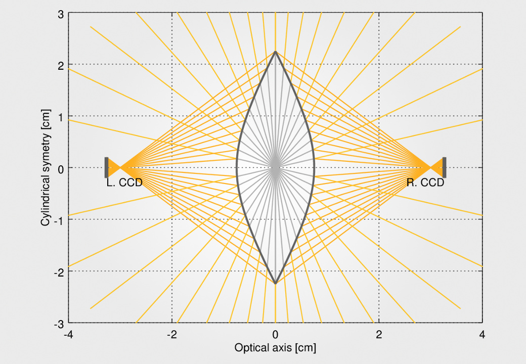
Examples of spherical camera designs obtained using different sets of parameters. The mirror is represented in gray as the two side sensors that capture the reflected light shown in orange - Images : Nils Hamel
Changing the parameters allows to modulate the size of the mirror, its thickness, the distance of the sensors to the mirror center and the size of the sensor themselves.
The proposed design is theoretical and ideal. Indeed, the light reflected by the principal mirror can not be collected by a sensor directly. The sensors can then be replaced by standard small cameras to produce the images. This solution was adopted in the ScanVan Project to produce a first prototype of the spherical camera based on the proposed design. The following images give a view of the built prototype :
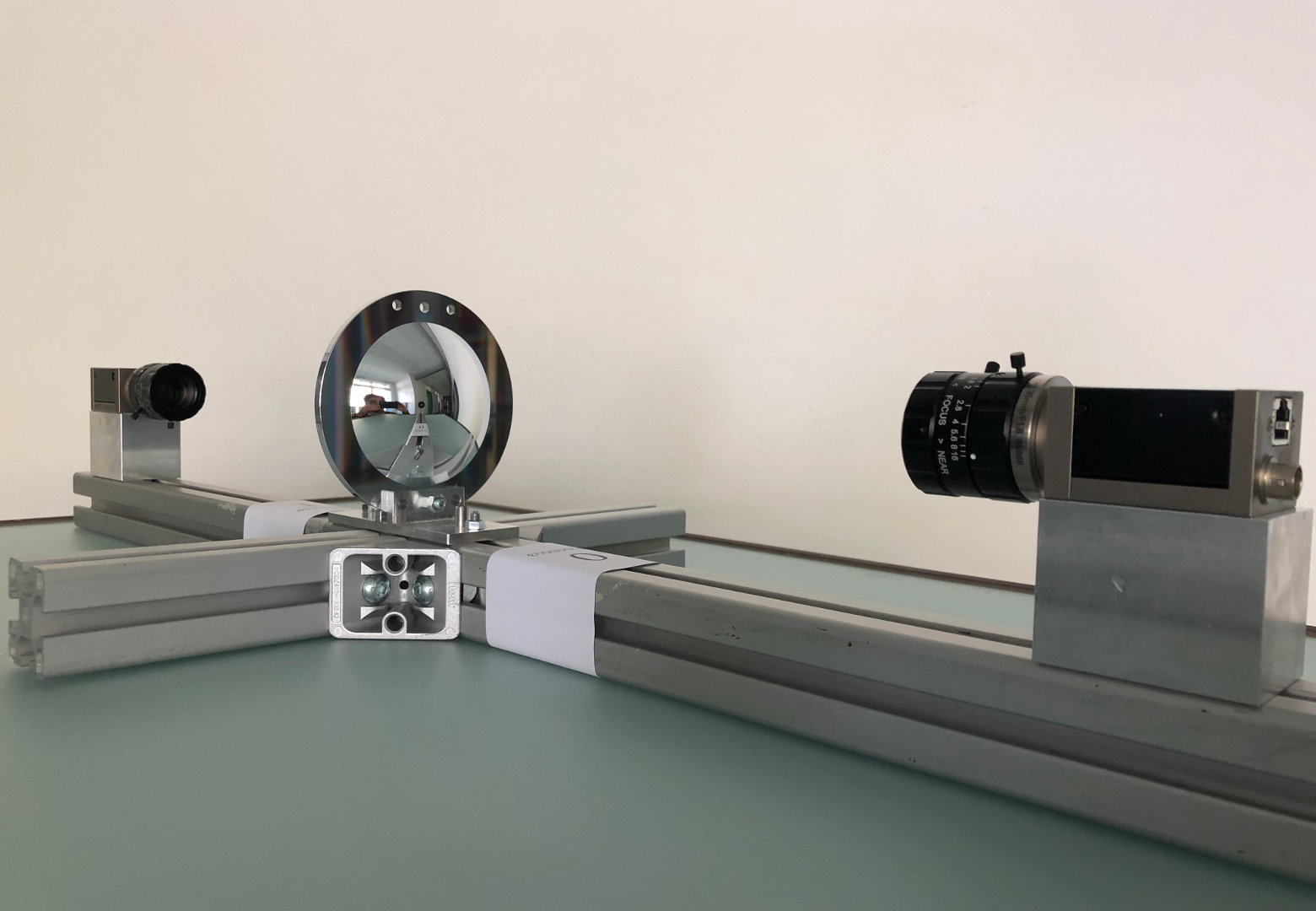

Spherical camera prototype built by Charles Papon & Marcelo Kaihara (HES-SO Valais) - Images : Marcelo Kaihara
As the sensors are replaced by traditional cameras, the device has to be calibrated in order to obtain the desired ideal images, usually represented using equirectangular mappings. The calibration procedure proposed in [3] was considered for the ScanVan Project prototype. The following image gives an example of the obtained capture using the calibrated prototype :

Example of device capture in equirectangular mapping (the camera parts and operator are removed from the image) - Image : Charles Papon & Marcelo Kaihara
Of course, the manufacture of the mirror and the mounting elements for the two side cameras used to capture the mirror reflected light induce reduction of the four pi field of view. Nevertheless, this prototype is able to considerably increase the field of view according to standard cameras and other omnidirectional devices, toward robust structure from motion pipelines. As a last element, the images captured by the camera produce perfect four pi panoramas without parallax effects
The pose estimation algorithm specific to images captured using a spherical central camera is designed to take advantage of the configuration of the camera, and more specifically of the absence of intrinsic parameters. The absence of intrinsic parameters allows to simplify the pose estimation problem, reducing it to the simple estimation of one rotation matrix and one translation vector.
Because the spherical camera is free of intrinsic parameters, the captures it produces can be identified to a simple projection on a unit sphere of the surrounding selected points. As for any pose estimation algorithm, matched features are considered for the pose estimation between two spherical captures. The input of the pose estimation algorithm is then a collection of corresponding points projected on the two unit spheres associated to the two cameras.
To estimate the pose between the two cameras, the algorithm uses an iterative application of the least-squares fitting of 3D point sets described in [4]. The following assumption is made : the point depths being lost after projection on camera unit spheres, it is assumed that the structure of the projections is sufficient to compute a first approximation of the rotation and translation to match the two point sets. With the knowledge of a first estimated rotation and translation, it is possible to correct the radii of the projections on the unit sphere through best intersection estimation between the matched features. In other words, the projections of the points are pushed away from the unit sphere along the iterations to retrieve the depth information. After each radii correction, a new rotation and translation is computed applying the [4] method. At the end of the iterations, the correct depth of the point is expected to be known, leading to a good estimation of the rotation and translation between the two cameras. The following images give an illustration of the situation at the last iteration of two theoretical cases :
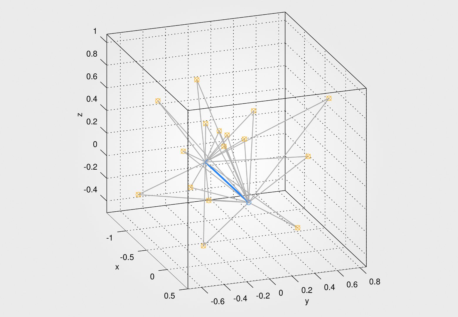
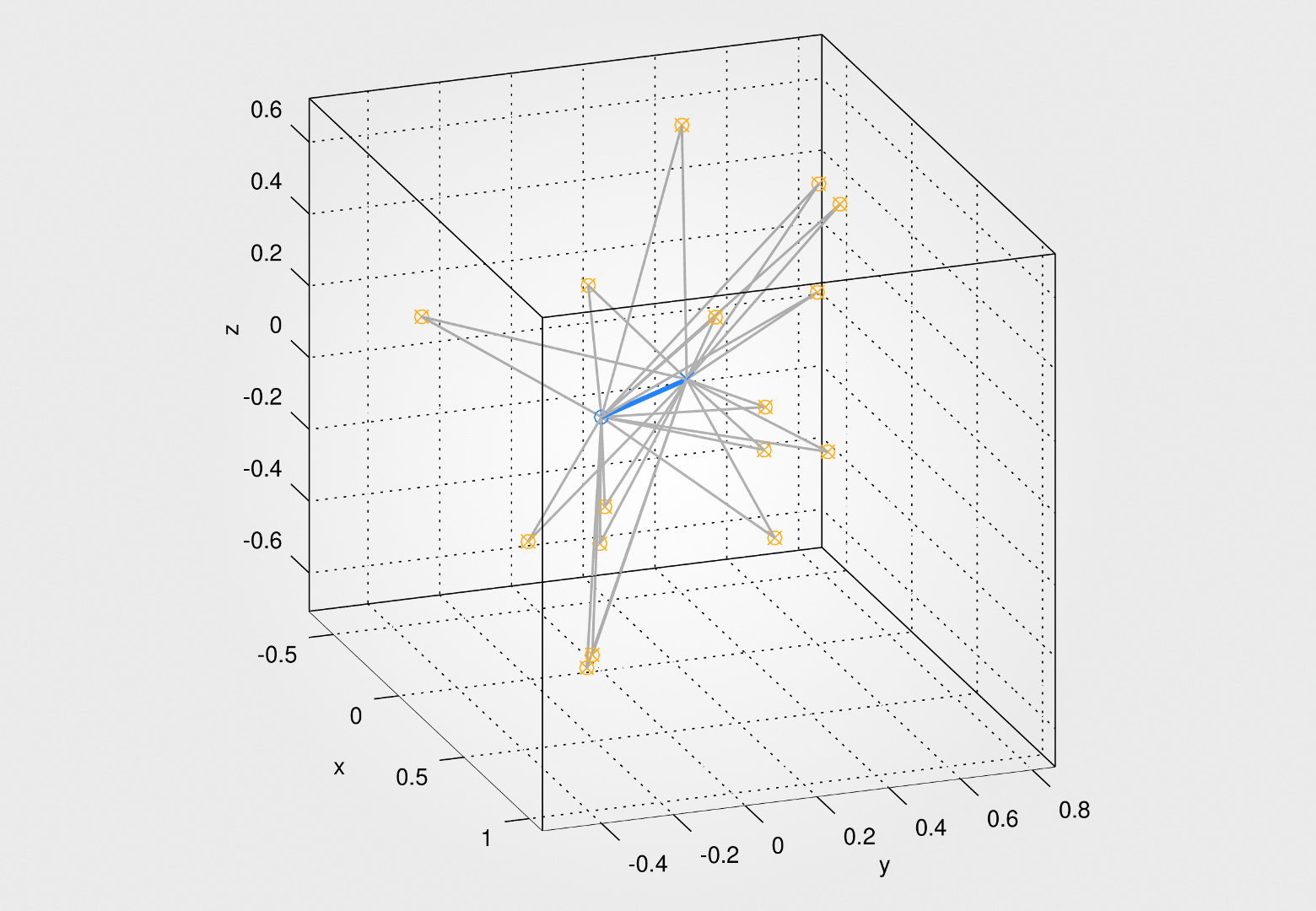
Algorithm last iteration state on theoretical cases : the blue line gives the vector between the two camera centers while the grey lines link the camera centers to the estimated position of the matched features - Images : Nils Hamel
The algorithm iterations stop condition is deduced from a characteristic of the algorithm design. As each matched feature has a projection on each camera, two sets of radii are corrected at each iteration. The convergence condition is, considering the estimated rotation and translation, that the radii of one matched features should lead to the same location, that is the position of the feature in space. The distances between the two positions defined by the two radii of the features can be used as an error function. Considering the largest error on a set of matched features, the algorithm stops as this value variation over two iterations goes below a tolerance value.
The following plots illustrate the convergence behavior of the algorithm on a simulated case using 32 features. The plot on the left gives the features maximum separation according to the iterations. This shows how the corrected radii are able to bring the features position away from the unit sphere to a common position in space. The plot on the right shows the error measures made on the estimated rotation and translation according to iterations (the true values being known in the case of a simulated situation) :

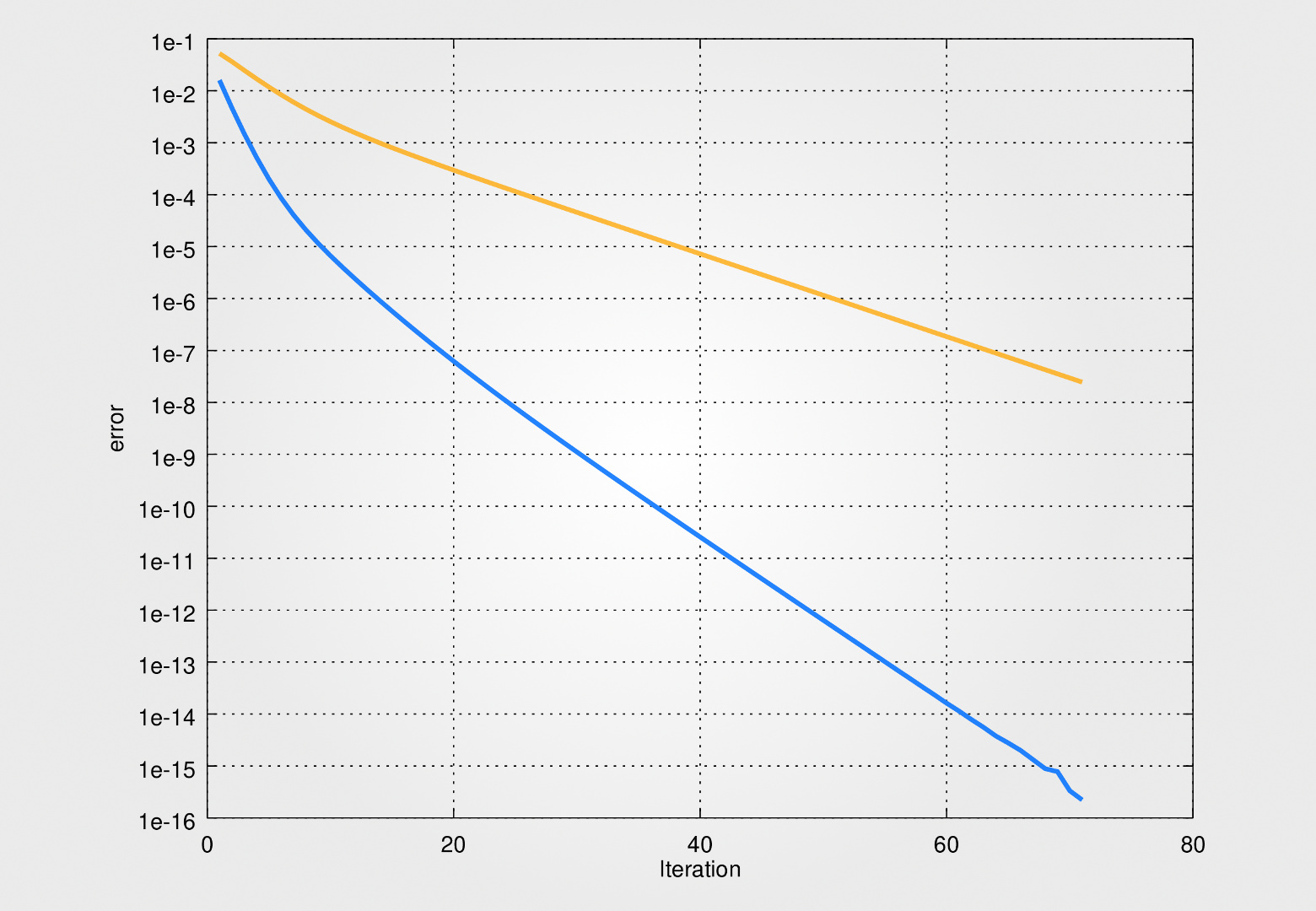
Features maximum separation according to iterations (left) and error measure on the estimated rotation (orange, right) and translation (blue, right) - Images : Nils Hamel
The error measure on rotation is computed by multiplying the estimated matrix with the transposed of the true matrix. The identity is subtracted to the result before to consider the Frobenius norm. The error measure on translation is more complicated as the scale factor is not known. The error is computed by taking one minus the dot product between the estimated translation and the true translation converted as unit vectors.
For stability reason, the pose estimation algorithm is augmented by a filtering procedure occurring at each iteration. This filtering process allows to remove a feature from the set as its position becomes statistically too different from the other features position. By removing such outliers, the algorithm become more stable even for badly conditioned situations.
The following plots show the ability of the pose estimation algorithm to resist to noise on matched features. They show how the error on estimated rotations and translations evolve with the addition of noise to the position of the matched features. The algorithm is used on random situations on which noise is added on position of the matched features. The amplitude of the noise is expressed as a multiplication factor of the norm of the true translation between the two camera captures. In addition, independent noise is added for both camera. The following plots show the error mean and standard deviation computed on 64 pose estimation for each noise amplitude using each time 32 matched features :
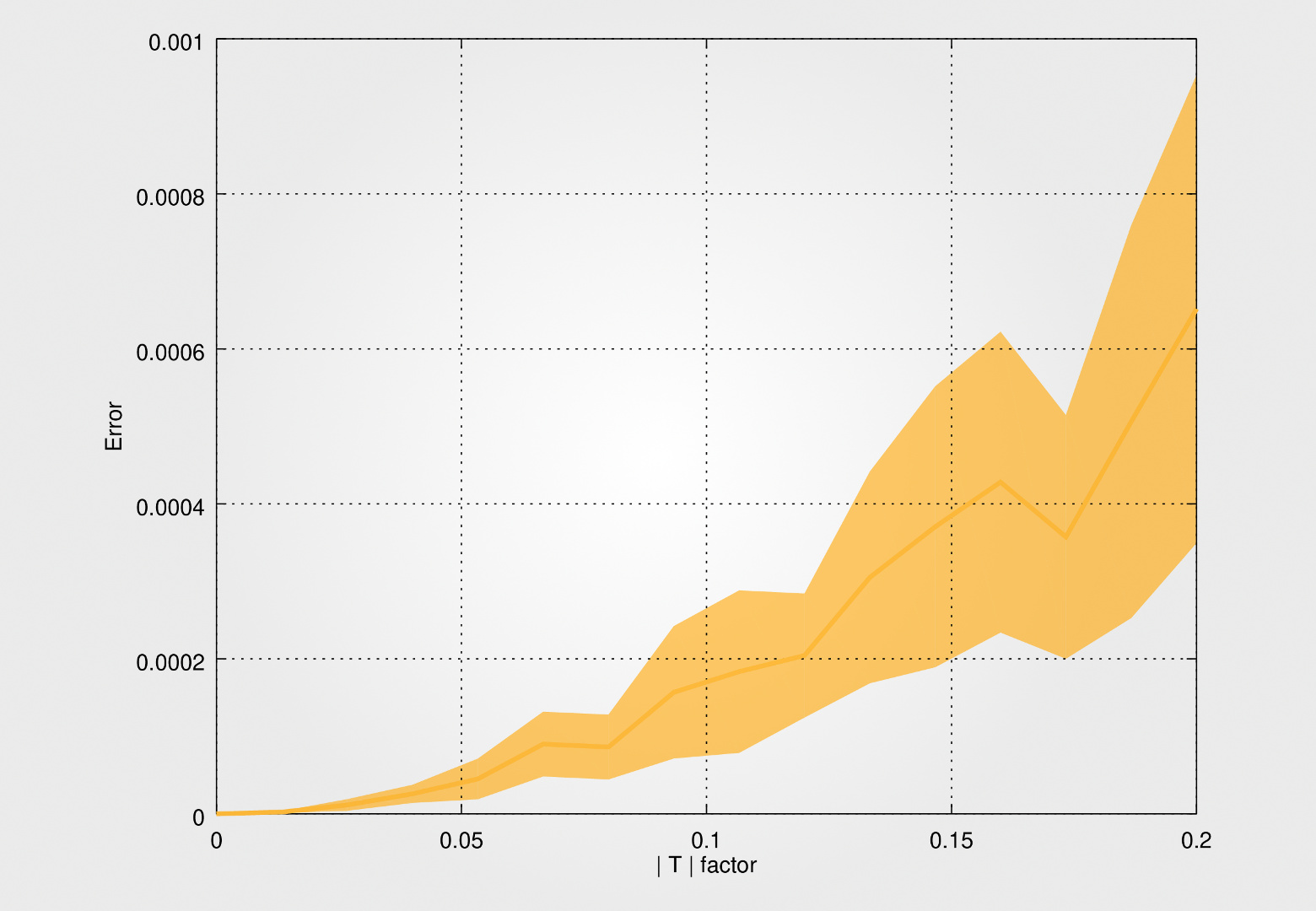

Error evolution according to noise amplitude on rotation (left) and translation (right) - Images : Nils Hamel
This shows that the algorithm is able to provide good estimation on rotation and translation even if all considered features are affected by noise.
The following plots show how the spherical approach is able to bring more precision on the estimation of the rotation and translation between the camera pose because of the distribution of features on the entire sphere. The experiment consists in two cameras that are getting closer to each other considering a set of features grouped in a sphere between the two cameras. As the cameras are far away from the center of the features sets, the scene is viewed by the cameras through a small angle of view. As the cameras get closer to each other, the angle of view of the features increases. It allows to illustrate how the stability and precision of the pose estimation evolve with the angle of view of the cameras. The following plots show the evolution of the pose estimation precision considering 16 and 32 matched features, 32 positions of the cameras and 32 different distributions of the features in the scene sphere :
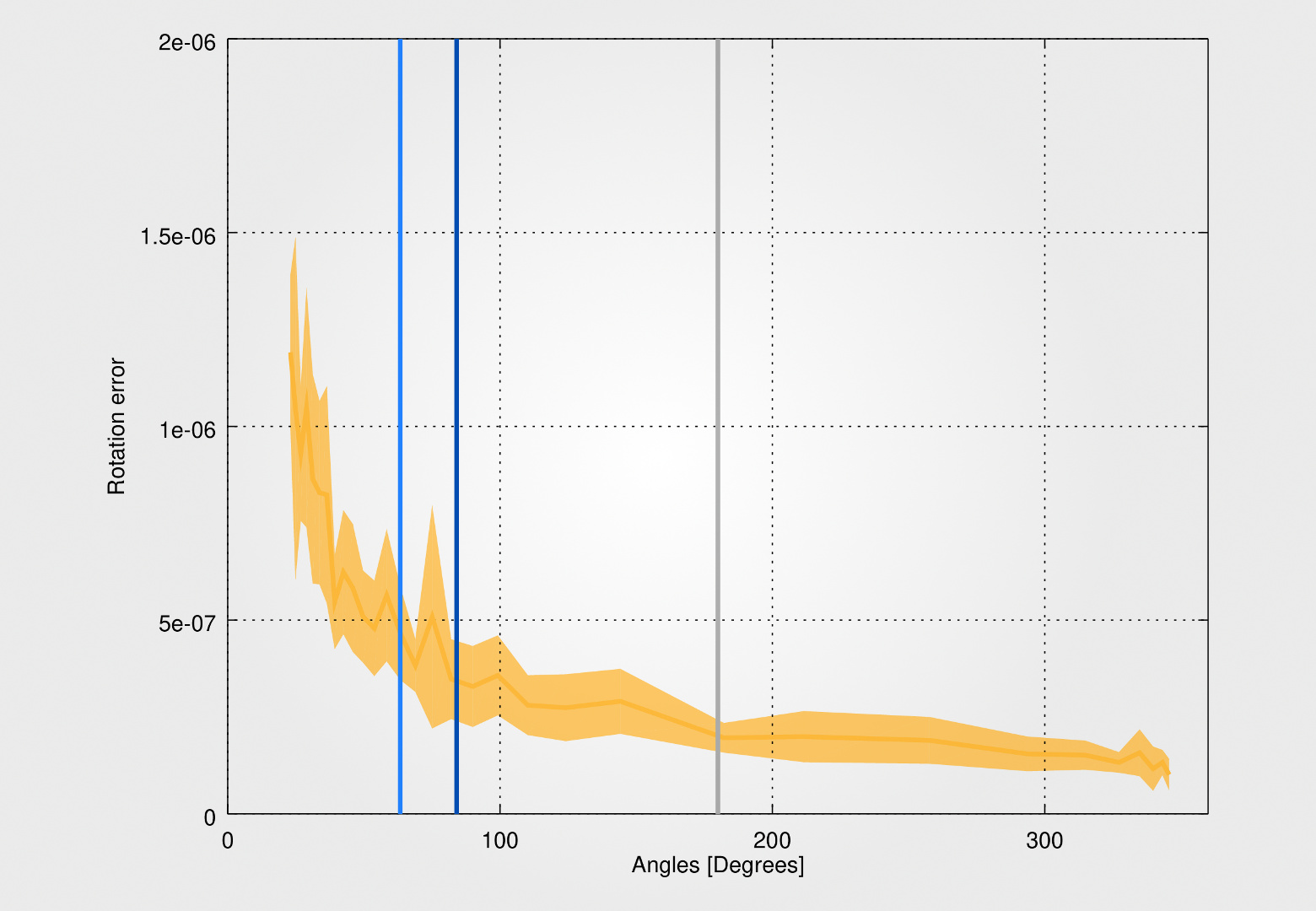
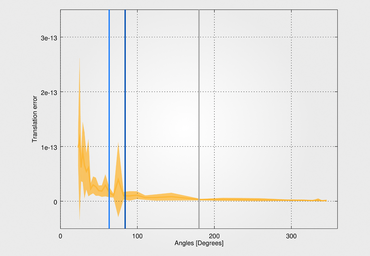
Evolution of rotation (left) and translation (right) estimation error mean and standard deviation according to the features angle of view. For each of the 32 points of measure, 32 different sets of 16 features are considered. The light and dark blue lines give the 36x24mm sensors 35mm and 24mm corresponding angles of view for comparison - Images : Nils Hamel
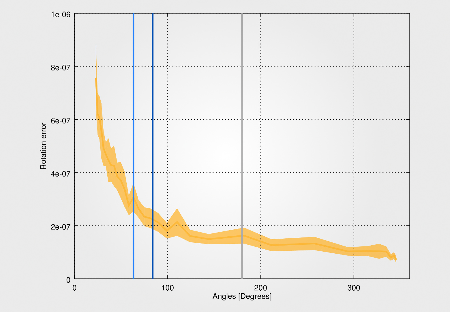

Evolution of rotation (left) and translation (right) estimation error mean and standard deviation according to the features angle of view. For each of the 32 points of measure, 32 different sets of 32 features are considered. The light and dark blue lines give the 36x24mm sensors 35mm and 24mm corresponding angles of view for comparison - Images : Nils Hamel
These results show how the increase of the angle of view is able to stabilize the estimation of the rotation and translation and to increase their precision. Such stability and precision are mandatory for large scale three-dimensional models computation to ensure contained drift on the visual odometry.
This overview of the algorithm exposes the main elements that shows how spherical cameras and algorithms are able to move structure from motion forward toward robust reconstruction pipeline and large scale models computation.
The spherical-camera comes with the following package (Ubuntu 16.04 LTS) dependencies (Instructions) :
- octave
spherical-camera - Nils Hamel
Copyright (c) 2016-2020 DHLAB, EPFL
This program is licensed under the terms of the GNU GPLv3. Documentation and illustrations are licensed under the terms of the CC BY 4.0.
[1] Shree K Nayar. Catadioptric omnidirectional camera. In Computer Vision and Pattern Recognition, 1997. Proceedings., 1997 IEEE Computer Society Conference on, pages 482–488. IEEE, 1997
[2] GANDHI, Tarak et TRIVEDI, Mohan. Parametric ego-motion estimation for vehicle surround analysis using an omnidirectional camera. Machine Vision and Applications, 2005, vol. 16, no 2, p. 85-95.
[3] Christopher Mei, Patrick Rives. Single View Point Omnidirectional Camera Calibration from Planar Grids. IEEE International Conference on Robotics and Automation (ICRA), Apr 2007, Rome, Italy. IEEE, pp.3945-3950, 2007
[4] ARUN, K. Somani, HUANG, Thomas S., et BLOSTEIN, Steven D. Least-squares fitting of two 3-D point sets. IEEE Transactions on Pattern Analysis & Machine Intelligence, 1987, no 5, p. 698-700.
