This is a repository of my solutions to Robotics laboratory homeworks, taken in the 3rd year at the Faculty of Mathematics and Computer Science, University of Bucharest. Each homework includes requirements, implementation details, code and image files
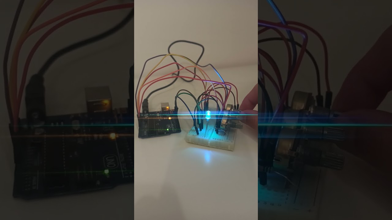
Homework 1 - RGB LED
- 1 RGB LED
- 3 potentiometers
- 1 resistor and wires as needed
- Use a separate potentiometer for controlling each color of the RGB LED: Red, Green, and Blue. This control must leverage digital electronics. Specifically, you need to read the potentiometer’s value with Arduino and then write a mapped value to the LED pins.

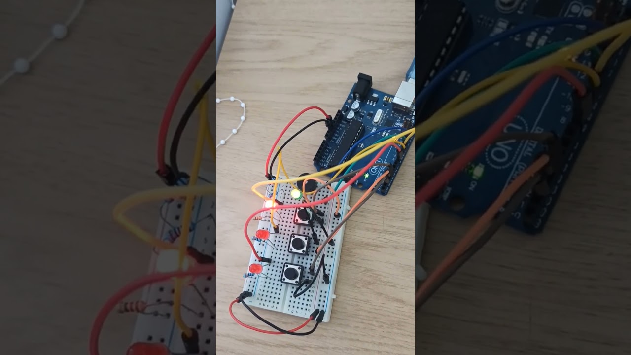
Homework2 - Elevator simulator
- 4 LEDs (3 for each floor and 1 for the elevator's operational state)
- 3 buttons for floor calls
- 1 buzzer
- resistors and wires as needed
- Design a control system that simulates a 3-floor elevator using the Arduino
platform. Here are the specific requirements:
- LED Indicators: Each of the 3 LEDs should represent one of the 3 floors. The LED corresponding to the current floor should light up. Additionally, another LED should represent the elevator’s operational state. It should blink when the elevator is moving and remain static when stationary.
- Buttons: Implement 3 buttons that represent the call buttons from the 3 floors. When pressed, the elevator should simulate movement towards the floor after a short interval (2-3 seconds).
- Buzzer:
The buzzer should sound briefly during the following scenarios:
- Elevator arriving at the desired floor (something resembling a ”cling”).
- Elevator doors closing and movement (pro tip: split them into 2 different sounds)
- State Change & Timers: If the elevator is already at the desired floor, pressing the button for that floor should have no effect. Otherwise, after a button press, the elevator should ”wait for the doors to close” and then ”move” to the corresponding floor. If the elevator is in movement, it should either do nothing or it should stack its decision (get to the first programmed floor, open the doors, wait, close them and then go to the next desired floor).
- Debounce: Remember to implement debounce for the buttons to avoid unintentional repeated button presses.
- Added a "decision-stack”. When using a normal elevator, you usually press multiple numbers and the elevator takes you there in order.
- I incorporated a linked list to keep track of every button pressed, creating a "decision-stack" feature.

Homework3 - 7 segment display drawing

You will use the joystick to control the position of the segment and ”draw” on the display. The movement between segments should be natural, meaning they should jump from the current position only to neighbors, but without passing through ”walls”.
- 1 x 7-segment display
- 1 x joystick
- Resistors and wires as needed
The 7-segment display should have the initial position on the DP (decimal point). The current position always blinks, regardless of whether the segment is on or off. The joystick is used to move from one position to its neighboring segments.
- Short pressing the button toggles the segment state from ON to OFF or from OFF to ON.
- Long pressing the button resets the entire display by turning all the segments OFF and moving the current position to the decimal point.

Homework4 - Stopwatch Timer

Using the 4 digit 7 segment display and 3 buttons, you should implement a stopwatch timer that counts in 10ths of a second and has a save lap functionality (similar to most basic stopwatch functions on most phones).
- 1 x 7-segment display
- 1 x joystick
- Resistors and wires as needed
- 1 7-segment display
- 3 buttons
- Resistors and wires as needed
The starting value of the 4 digit 7 segment display should be ”000.0”. Your buttons should have the following functionalities:
- Button 1: Start / pause.
- Button 2: Reset (if in pause mode). Reset saved laps (if in lap viewing mode).
- Button 3: Save lap (if in counting mode), cycle through last saved laps (up to 4 laps).
- Display shows ”000.0”. When pressing the Start button, the timer should start.
- During timer counter, each time you press the lap button, you should save that timer’s value in memory (not persistent, it is OK to be deleted upon reset), up to 4 laps (or more if you want); pressing the 5th time should override the 1st saved one. If you press the reset button while timer works, nothing happens. If you press the pause button, the timer stops.
- In Pause Mode, the lap flag button doesn’t work anymore. Pressing the reset button resets you to 000.0.
- After reset, you can now press the flag buttons to cycle through the lap times. Each time you press the flag button, it takes you to the next saved lap. Pressing it continuously should cycle you through it continuously. Pressing the reset button while in this state resets all your flags and takes the timer back to ”000.0”.

Homework5 - Pseudo-Smart Environment Monitor and Logger

Develop a "Smart Environment Monitor and Logger" using Arduino. This system will utilize various sensors to gather environmental data, log this data into EEPROM, and provide both visual feedback via an RGB LED and user interaction through a Serial Menu. The project focuses on integrating sensor readings, memory management, Serial Communication, and the general objective of building a menu.
- Arduino Uno Board
- Ultrasonic Sensor (HC-SR04)
- LDR (Light-Dependent Resistor)
- RGB LED
- Resistors as needed
- Breadboard and connecting wires
-
Prompt for a value between 1 and 10 seconds. Use this value as a sampling rate for the sensors. You can read a separate value for each or have the same for both.
-
Prompt for a threshold value for the ultrasonic sensor. You can decide if that is the min or max value. When the sensor value exceeds the threshold value, an alert should be given. If the LED is set to Automatic Mode (see section 4.2), it should also turn red if any of the sensors are outside the value.
-
Prompt for a threshold value for the LDR sensor. You can decide if that is the min or max value. When the sensor value exceeds the threshold value, an alert should be given. If the LED is set to Automatic Mode (see section 4.2), it should also turn red if any of the sensors are outside the value.
-
Return to the main menu
-
Continuously print sensor readings at the set sampling rate, from all sensors. Make sure you have a way to exit this (such as pressing a specific key) and inform the user of this method through a message.
-
Displays the sampling rate and threshold value for all sensors.
-
Displays the last 10 sensor readings for all sensors. (or be creative and do it another way).
-
Return to the Main menu.
-
Set the RGB colors manually. You decide how to input them, either by making an option for each channel or by putting a string, etc. If you expect a specific format, make sure to inform the user.
-
If automatic mode is ON, then the LED color should be GREEN when all sensors value do not exceed threshold values (aka no alert) and RED when there is an alert (aka ANY sensor value exceeds the threshold). When automatic mode is OFF, then the LED should use the last saved RGB values.
-
Return to the main menu


Homework6 - Mini 8x8 LED Matrix game

I developed a small game on an 8x8 matrix. In the game, I included three types of elements: a player (blinking slowly), bullets (blinking fast), and walls (not blinking). The basic idea was to generate walls on the map (occupying 50% - 75% of the map), and then I could move around with the player to destroy them. I implemented it in a Terminator-tanks style. The game map can be dynamically adjusted to any size, but it is displayed on the 8x8 matrix in the form of a fog of war. This adds an extra layer of strategy, allowing players to explore the map as they progress.
- Arduino Uno Board
- Joystick
- 8x8 LED Matrix
- MAX7219
- Resistors and capacitors as needed
- Breadboard and connecting wires
- Move Up: Gently push the joystick upwards to navigate the player character upward on the matrix.
- Move Down: Similarly, a subtle downward movement of the joystick guides the player character downward within the matrix.
- Move Left: Tilt the joystick to the left to smoothly shift the player character horizontally to the left.
- Move Right: Conversely, a tilt to the right accomplishes a seamless movement of the player character to the right.
- Shoot: Press the joystick to initiate the shooting action, releasing bullets to destroy obstacles and progress in the game.
These responsive joystick controls enhance the gaming experience, providing dynamic and engaging maneuverability for the player.

Homework7 - Mini 8x8 LED Matrix game - Update

- When powering up the project, a greeting message should be shown until the joystick is pressed
-
- Start game
- Settings
- About
- When the game ends, add a message. Wait for a button push from the user, before returning to main menu again.
-
- I've implemented a dynamic health system in the game. The player's life decreases over time, and relevant details, such as the remaining lives, are displayed. To enhance longevity, players receive additional lives by successfully turning off LEDs.
- The game gracefully concludes when the player's life reaches zero. In the event of successfully "destroying" all LEDs, the game also ends. A concluding message is displayed, awaiting user input. Upon user interaction, the game seamlessly returns to the main menu.
