mariuszhermansdorfer / sandworm Goto Github PK
View Code? Open in Web Editor NEWAugmented Reality Sandbox for Grasshopper & Rhino
License: MIT License
Augmented Reality Sandbox for Grasshopper & Rhino
License: MIT License

![dependabot[bot] avatar](https://avatars.githubusercontent.com/in/29110?v=4 "dependabot[bot]")


Will likely involve splitting or augmenting Core.cs and shifting a number of constants regarding FoV/resolution into some sort of manager.
This is extremely nit-picky and low-priority, but I find that the reset / calibrate options as presented in the UI are slightly confusing and might be difficult for new users to grasp.
Unless I'm wrong, the calibrate method is essentially a one-time trigger, e.g. it samples the latest frame and averages the values to identify a good elevation number. However, as presented in the UI, the button is a checkbox which would normally indicate some sort of boolean state that is persistent.
The reset action is also a one-time trigger, but is presented in a different way: as a boolean input type. Although it has some help text, it may not be apparent to all users that the Button component is what's needed to trigger the action.
A suggestion here would be to shift both of those triggers to be shown in the same way, perhaps as buttons within the Sensor rollout. That could also be useful to clarify the role of the reset button as re-setting-up the mesh processing rather than a 'clear to defaults' for the parameters of the analysis/processing/etc.
It doesn't look like there's a button widget in CustomComponent but I could try and adapt the one I made for Caribou perhaps.
This would be pretty far down the list of priorities, but I thought I'd put it out there while I have the link in front of me. Google has published a colormap library for depth images that more uniformly maps between color bands and spatial bands. In an ideal world the gradient used to color the pixels would be entirely user-controlled, but this might be an interesting option to consider as a robust default.
Calling into the AnalysisManager to get lookup pixel colors is significantly slower (across the loop's course) than the previous method which had a direct lookup of a color table which was local to SolveInstance(). Ideas for improving performance here while keeping the abstractions from the analysis classes:
GetPixelColor for each analysis type as a delegate method before entering the loopI'm not very clear as to the relative low-level performance differences between different options here so will play around and see what works best. As we are dealing with pretty small differences in time I might try and make some mock functions that can simulate the process of coloring the per-pixel loop in a way that can be more easily run multiple times and averaged. I had a go at using benchmark do net for this, but didn't have any luck integrating it as either a console app (which then couldn't call into rhino common) or as a separate plugin (which then couldn't instrument methods within SolveInstance). Maybe the dotTrace profiler will help.
Update all the necessary credit information & link to developers who contributed their logic.
Implement smoothing on the point cloud directly. Currently Gaussian blurring is referenced but not implemented.
There are Grasshopper plugins, which allow to perform landscape analyses on various meshes, Bison being one example.
Great as they are, their performance is not good enough for real-time interaction with the Sandbox, a slope analysis takes approx. 400ms on a typical mesh coming from SandWorm.
Implementing the algorithm directly in the C# code will be much faster. Current implementation of elevation banding takes 15ms, slope should be in the same ball park.
Use the logic described here.
Not sure if this is a weird artefact of my setup, but the font size values (and perhaps UI dimensions more broadly) seem much overscaled in Grasshopper. This creates some clipping in the dropdown menus. This is at 200% UI scale on a 5120x2880px screen.

Add a simple agent simulation that randomly places agents on the periphery and gives each agent a random destination.
Using the slope analysis agents as data agents should wander to their destinations preferring more walkable slopes along the way.
This could later be elaborated to make use of the data the sensor collects.
It is possible for Grasshopper components to offer toggles in their right-click 'contextual' menus. While in general it's useful for parameters to be explicit as inputs, I think there's a case to be made that the different options for coloring the mesh made by Sandworm would be better placed within a menu rather than a parameter with a magic number. Doing so would be easier to interact with and I don't think there is an obvious use case for the color style to be parametrically controlled. Implementation is pretty simple and described here.
If implemented, the baseline options could include:
Additional options that could be presented as toggles within that same list:
This implementation wouldn't provide a means to more explicitly control any parameters in the above options. Some currently-hardcoded parameters (like max depth/height) wouldn't apply to all of them either. A dedicated 'color options' component, as used by Ladybug and the like, could potentially be used for this kind of flexibility if/when the defaults need to be more explicitly controlled. The other option might just be to have separate components for each flavour of analysis and then directly expose relevant configuration options as parameters.
@philipbelesky, @BarusXXX let's start a new thread about this.
It took me a while, but I think I've finally wrapped my head around how Kinect Azure understands the world. Here are some important facts:

Transforming from depth camera space to RGB camera space results in the amount of pixels equivalent to current RGB camera mode. This is overkill for our use case, especially if we consider, that the resulting pixels are interpolated, hence don't add any meaningful information (reference)
Transforming from depth camera space directly to a point cloud keeps the amount of pixels and results in undistorted 3D geometry. Under the hood, a lookup table is generated for each 2D depth pixel with a translation vector defining the XYZ coordinates of resulting 3D points. (reference)
Unfortunately, there is a lot of jitter in the depth signal, which results in pixels 'jumping' on the XY plane. To counter for it, we previously used a fixed rectangular grid generated when 'sensorElevation' was set, and subsequently changed only the Z values of this grid. Kinect Azure doesn't have rectangular depth output which makes our task less trivial but we can 'undistort' its depth image by leveraging the lookup table mentioned above (reference)
Once 'sensorElevation' is set (either manually or through the calibration process) we need to calculate the 'ideal' XY spacing of our 3D pixels. The aforementioned camera tilt needs to be taken into consideration here. We generate another lookup table, where we store individual pixel's vertical deviation per unit of Z elevation. Then we create a 'fake' depth map with 'ideal' uniform elevations (this doesn't mean that individual pixel values are identical, but they correspond to a 'flat' plane) and pass it to our transformation logic to obtain 'ideal' XY coordinates for given 'sensorElevation'.

Side view before:
Side view after:

There are some outliers, but it's close enough to accept as final solution:
I have a working prototype branch on my machine. Will clean up the code a bit and publish to the repo on Monday.
Colorize mesh faces according to their elevation on the vertex level
m.Vertices.AddVertices(pts); m.VertexColors.SetColors(colors);
More info here
I have added a handle for the kinect type for calibration in my latest commit ebb1c3d,
However I am checking the runtime with breakpoints and runningSum Array is a Null throughout the calculation here...
SetupKinect uses the elevation array to populate the runningSum if it is null? But elevation array is null at the moment runningSum is needed, so runningSum is also null... (maybe this is the issue)?
What function should be bringing it into the scope?
Add option to recreate an existing terrain in sand based on GIS information.
This could also be used to graphically visualize cut & fill differences between design iterations.
Some of the operations in SolveInstance() need to happen in a serialised order, while others are somewhat non-linear. The most important of these is probably the call to CreateQuadMesh which can proceed as soon as the pointCloud is processes as the mesh is not referenced further until the end of the definition, or if a relevant analysis requires the entire mesh as a parameter. Shifting that call to be asynchronous might help performance (particularly when using a relatively slow piece of analysis) as each code path can run in parallel.
This is just an idea for now, although I know c# has good async/await support. There may be further scope for using asynchronous paths with the renderBuffer or perhaps even scope to split out the mesh construction and mesh coloring steps so that each can proceed asynchronously (assuming that would be faster than having a single step).
@philipbelesky, @BarusXXX do you see any value at all in outputting stats about how fast certain parts of the code were executed? It was good for debugging purposes, but IMHO could be safely removed now.
With the new CutFill analysis mode, we started presenting more meaningful information through this channel. Any other suggestions for what we could spit out here?
As mentioned in #1 - we need a dedicated SW component outputting the point cloud
@philipbelesky, @BarusXXX, since we are all in academia, let's think of ways to get some credit for our work on SandWorm. Should we write a paper? Submit a poster? Attend a conference?
So much has been done on the sandbox front already so we would have to come up with a good storyline. Opening this one up for brainstorming and discussion.
The Z scaling of the generated depth map has wrong proportions in relation to the size of the X Y, @mariuszhermansdorfer mentioned that what is coming out of the camera should be in mm so if the value in the image ushort cast to int is 200 this would mean that the object is 200mm away from the camera? The values I am getting from the depth camera seem to have the wrong z scaling.

As regards to culling, @mariuszhermansdorfer how had you avoided getting cascade effect (due to sudden change in z see above) if some of the objective points have Z=0. Or you you simply show the scene from the top?
This came up in #44 but potentially affects much more than that branch. Currently most Sandworm components used camel case for parameter names; aside from those being added in #44. To the extend native Grasshopper components use more than one word, they do so using a space. There are some prominent exceptions to this though (i.e. in Kangaroo).
I have a mild preference for not using camel case, but happy to go with either option if consistent.
On a similar note SandWorm itself is pseudo-camel cased, but its namesake is "sandworm". Would it be ok to change that also (at least for the component names; I don't think class names etc would need to follow that convention)
This might be stretching the limits of what is possible to do within the performance budget of a definition, but other sandbox style applications seem to intelligently 'pause' updating a mesh when users are reshaping the sand with their hands. This gets around some of the oddities that come with the mesh suddenly updating to incorporate hands as if they were part of the landform.
The Kinect has APIs for hand/limb detection, so one way to go might be divide the pixels into a clustered grid (via an R-tree?) and skip updating those depth pixels as long as there is a hand present within the grid.
During our recent PhD workshop Kane operated a robotic arm to form the sand in the box. It would be great to create a dedicated component allowing for an intuitive plug-and-play type of interaction with the UR robots.

There 2 places where I could not generalize the access to kinect Type variable currently selected by the user;
Here;
And setting the depth mode Here;
Using the depth mode fetching implimented here;
These need to reference the active kinect type by the user.
Idea for future: We should be able to detect the kinect type currently connected, and only give the user access to different depth modes.
It is often quite difficult to see that a point cloud is working properly because (in my experience) it comes into Rhino - usually less than 5mm x 5mm. Rhino's camera also behaves oddly when dealing with such small units and this often makes it difficult to navigate around the point cloud.
I'm not sure if the Kinect SDK can report in real-world units, or if this is just a mismatch between the assumed units the SDK reports and the coordinate system in Rhino. Even if scaling to the model's true size is not possible it would be nice to scale up by a generic quantity such that the point cloud is more at the scale of meters rather than mm.
Happy to investigate and add a PR, just wanted to check-in to see if this is was a desirable behavior.
Create separate components for:
The point of this is for users to be able to automatically (and precisely) define the input for the sensorElevation variable. This logic could also output a depth scan of the flat table to correct for Kinect inaccuracies and sensor tilt.
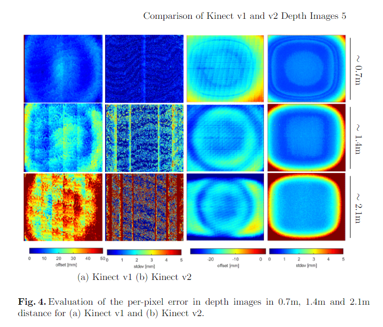
Technical background in this paper.
The use case here is to be able to scrub backwards in time in order to examine how the sand/mesh changes over a particular period. The immediate use case I have for this is an analog simulation of dune drift (basically by way of pointing fans at the sand). For that purpose, I would want to capture a sequence of meshes over a given time period to visualise the change and be able to perform analysis between the different states. This would likely have value in other forms of simulation — e.g. a Cantrell-style setup for fluvial processes.
Being able to set the tick rate helps here, and data dams help further, but it would be ideal if the outputMesh list was able to be added to by successive solves rather than replacing each solve. That should be easy enough, my question is whether it should be in the main component (with an additional option in SandWormsetup? I'm imagining a simple IntegerParameter along the lines of 'stored frames' which, if set, appends new meshes to outputMesh up to a certain size. If that size is hit, the earliest items in the sequence start getting removed.
I'm running a workshop with this use case in mind this week, so should be able to sketch out an implementation and PR based on how that goes.
Hey @philipbelesky, it seems I have merged your most recent PR a bit prematurely. Got to test it with the Kinect just now and it doesn't seem to be working properly. Please see the linked video. Tried both in meters and millimeters with the same result.
Also, the new method is much slower than the previous one (20-25 vs. 1-3 ms). Disabling the call to Analysis.AnalysisManager.GetPixelColor(depthPoint) makes things snappy again.

Could you please have a look at this?
As mentioned in #1 we need a dedicated component for RGB/QR code token isolation
Currently the logic to calculate a gradient ramp and colorize all the mesh vertices takes about 15ms. Explore faster ways of doing this.
@BarusXXX, @philipbelesky, as you know, I've recently completed another Grasshopper project - GreenScenario. It uses custom UI elements to flatten the learning curve for newbies. Now, I'd like to adopt the same UI for SandWorm. Here are the basic elements in collapsed (left) and expanded views:

My suggestion would be to go with the following structure:
Traditional Grasshopper Input Parameters:
Group: Sensor
Group: Analysis
Group: Post-Processing
Traditional Grasshopper Output Parameters:
Doing this would allow us to merge three components into 1 (Options, Mesh, Point Cloud) and have a plug & play setup, which shouldn't present a barrier to beginner users. I've left out the TickRate and KeepFrames parameters. Would you like to keep them, and if so why?
Am I missing any other functionality? Would this change break any of the existing workflows with Fologram or color markers?
Currently the ComputeLookupTables methods of each analysis option are calculated each time the definition solves which seems inefficient. To cache the values we will need to track the relevant user parameters that could alter the table (i.e. sensorheight, waterlevel) and only re-compute the tables if a relevant parameter changes. Each class inheriting from MeshVisualisation will likely have a distinct logic for doing so as they depend on different inputs (or none at all in the case of slope/aspect).
Bundle Microsoft.Kinect.dll and any other external dependencies into the GH component.
@philipbelesky, you suggested this one a while back. Can't find the discussion thread, where it was mentioned...
@philipbelesky, @BarusXXX let's define the minimum product we want to release as version 1.0 and start working towards a deadline sometime in October maybe?
I have combed through the list of open issues and labeled some with a corresponding milestone tag. Feel free to add to it and assign yourself to whichever suit your fancy.
Edit:
Created a Kanban style board to better track the progress. While creating new issues, just assign these to the relevant project.
This a bit premature given #44 hasn't landed, but I'm waiting on VS to update so here is the idea:
The MeshCompareComponent would take an optional list of points. These would be projected on to the mesh, in a similar manner to the cropping tool. and also passed to the main component. The main component then would compare the difference in elevation between the comparison mesh and the live mesh. To visualise this it would draw a line between the two and/or provide a numeric read out.
The idea/value here is based on the following:
Changing the average frames value often (particularly if reducing the value) shifts the Z-axis. Reducing the average frame value shifts it more downwards than reducing increasing the average frame value shifts it upwards. The new position persists until the definition is reloaded. This occurs regardless of analysis type.
Haven't had a chance to dig into this extensively, but it seems like the block withrenderBuffer.Clear(); is not being triggered when it should be (presumably on an averageFrames input change). Does that mean an internal cache of averageFrames needs to be kept so that it can be explicitly compared to the parameter value in order to detect differences? This is how I assumed I would implement #30, but idk if there is a more elegant way to check for changed parameters between solves.
Start brainstorming about how to best approach water flow analysis on the mesh.
Trying to use tokens with Fologram point and area markers. After I connect a device to fologram there is still a solution exception:Could not load type 'OpenCvSharp.Mat' from assembly 'OpenCvSharp, Version=1.0.0.0, Culture=neutral, PublicKeyToken=6adad1e807fea099'. Version error perhaps?
Drawing actual curves to display contour lines is computationally expensive. Let's try adding these in the shader instead. Simply change the vertex color value to black at a given interval in the Z direction.
When heavy analysis are chained to the SandWorm component it might slow down the UI. Maybe offloading it to a separate thread would prevent the UI thread from locking.
a workaround for now is to use a data dam + a timer to only calculate these analysis at a user specified interval.
@philipbelesky, @BarusXXX I recently started looking into Rhino plugin development to develop my skills further.
Would you see any benefit in converting SandWorm from Grasshopper to Rhino? Would it lower the bar for students' adoption, or just kill the purpose of introducing them to a wider set of computational design tools?
Am curious to hear your take on it.
As a side note, here are my early doodles with custom UI styling for Rhino panels. Let me know if you'd like to use it for some of your projects:
Test different smoothing algorithm (gaussian blur, weighted average, etc) and implement the best to work directly on the depth array.
We need to think if the transformation from depth camera to color camera is needed, also what is the difference if one gets the depth camera and transforms it to color camera using;
transformed_depthimage = transformation.DepthImageToColorCamera(capture)
array instead of the grabbing the Z value after transforming the depth imageto a pointcloud via;
transformation.DepthImageToPointCloud(depthImage, CalibrationDeviceType.Depth) //the last argument is default so you can omit
or if you have the transformed_depthimage you can use;
transformation.DepthImageToPointCloud(transformed_depthimage, CalibrationDeviceType.Color)
since the output after each of these is a image, you can access the underlying array with;
myImage.GetPixels().ToArray()
We need a way to inform future users on what SandWorm can do and how to get there. Some ideas:
Line 149 of SandwordComponent.cs contains the condition:
if (p.Z > dep || p.Z < 1.0)
This was a stumbling block in getting the model operating as the <1.0 was culling a bunch of points that contained the relevant parts of the cloud. Does 1.0 have any particular meaning in terms of units? Maybe this is because I had the model further/closer than I should?
Anyway, it seems like the ideal way to provide a depth cull would be to provide either a depth min and depth max parameter, or to accept a Domain. Not sure what the best approach is and it might be worth implementing alongside #1 - if not I'm happy to add a PR for it.
Replace the current triangulation method:
Mesh.CreateFromTessellation
with
Mesh.Faces.AddFace
as suggested in this discussion thread
Pretty self-explanatory. The code paths are all in place, it just needs an implementation in Aspect.cs along the lines of Slope.cs.
As simple as that - we need a set of icons for our components.
A declarative, efficient, and flexible JavaScript library for building user interfaces.
🖖 Vue.js is a progressive, incrementally-adoptable JavaScript framework for building UI on the web.
TypeScript is a superset of JavaScript that compiles to clean JavaScript output.
An Open Source Machine Learning Framework for Everyone
The Web framework for perfectionists with deadlines.
A PHP framework for web artisans
Bring data to life with SVG, Canvas and HTML. 📊📈🎉
JavaScript (JS) is a lightweight interpreted programming language with first-class functions.
Some thing interesting about web. New door for the world.
A server is a program made to process requests and deliver data to clients.
Machine learning is a way of modeling and interpreting data that allows a piece of software to respond intelligently.
Some thing interesting about visualization, use data art
Some thing interesting about game, make everyone happy.
We are working to build community through open source technology. NB: members must have two-factor auth.
Open source projects and samples from Microsoft.
Google ❤️ Open Source for everyone.
Alibaba Open Source for everyone
Data-Driven Documents codes.
China tencent open source team.