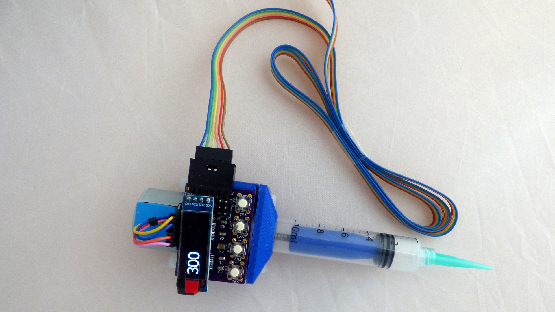
This is a solder paste dispenser. The controller supports unipolar and bipolar stepper motors, a foot pedal switch, an OLED display, a LED that blinks faster when the motor runs faster, and a menu system. The board has been designed with easy soldering in mind, using components size 0805 and up.
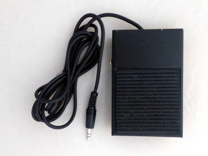 Dispensing can be initiated either by pressing the push button on the dispenser, or by pushing down a foot pedal switch.
A foot pedal switch has the advantage that it frees up a hand. Using a foot switch is also more stable; pushing a button on the solder dispenser always moves the syringe tip a little bit.
Suitable foot pedals are Adafruit product ID 423 and Sparkfun COM-11192, and their equivalents at ebay and aliexpress.
These foot pedal switches are simple on/off switches, normally open. Speed controller foot pedals with a potentiometer will not work.
The display shows the motor speed.
The OLED display is a generic OLED module 0.91" diagonal, 128x32 pixel, I2C, SSD1306, as found on ebay, aliexpress and others. Before buying, check the module has a 4-pin connection - GND, VCC, SDA, SCK - and uses a SSD1306 controller. The display ought not to touch any of the components below, but you can always put a bit of Kaptan tape on the back of the display, just to make sure.
The OLED display is optional. If you choose not to install the OLED display you can still check stepper speed on the serial console.
There is a settings menu on the serial port. The serial port runs at 115200, 8N1, no flow control. Access the menu using a vt100 ansi terminal emulation, e.g. PuTTY on Windows, or minicom on Linux. On Android, use an USB OTG adapter and Serial USB Terminal. The settings menu allows you to configure forward speed, backward speed, pullback, and microstepping, and to store and recall these settings from non-volatile memory. The menu looks like this:
[f] Forward speed 125 steps/sec
[s] Forward steps 0 steps
[b] Backward speed 500 steps/sec
[d] Pullback delay 2000 millisec
[p] Pullback steps 0 steps
[m] Microstepping 2
[n] Profile number 0
[r] Restore profile
[w] Save profile
[h] Help
Forward speed can be set using the faster/slower buttons on the dispenser itself or using the console menu.
If forward steps is zero, the syringe plunger is pushed down as long as you press the push button or the foot switch pedal. This is useful for making beads, and the normal setting when dispensing solder paste. If forward steps is non-zero, pushing the forward button or the foot switch moves the plunger down exactly the number of steps in the settings. This is useful for making precise, repeatable dots, e.g. as a glue or lubricating oil dispenser.
Backward speed can only be set using the console menu.
Sometimes liquid keeps oozing out after you stop dispensing. If pullback steps is non-zero, then after a pullback delay period of inactivity the plunger will move back pullback steps, to stop liquid oozing out. How successful this is and how many steps the plunger needs to pull back to stop the oozing depends upon the viscosity of the liquid. Pullback works better with low viscosity liquids than with high viscosity paste. Pullback is interesting if you use this as a dispenser for e.g. cyanoacrylate glue.
The controller supports up to 1/64 microstepping. This is open loop voltage control microstepping. Choose speed and microstepping that goes well with your stepper motor. This may take a bit of trial and error. Default is half-stepping, suitable for 28BYJ-48 steppers .
Once you have found a setting that works, you can save it for later. Up to five profiles can be saved. These profiles are remembered even when the power is turned off. After power-up the last saved settings are used.
If you want to play it safe, use a 5.0V 1A phone charger as power supply. The TB6612 stepper motor driver IC supports 5V 1.2A continuous, but can be damaged by higher currents. Using a power supply with a maximum current less than 1.2A protects the driver IC in case of short circuit or stall.
The voltage range is 4.5V to 5.5V. More than 5.5V is too much for the atmega328p microcontroller; less than 4.5V and the TB6612 stepper driver stops working.
The board has a MOSFET for reverse polarity protection.
The controller board has four headers:
- J1 is the ISP connector for downloading the initial firmware to the atmega microcontroller.
- J2 connects to an USB to serial adapter (pins +5V, RX, TX, GND) and the footswitch (pins FTSW, GND). The footswitch is optional, but very handy.
- J3 is the connector for the stepper motor. Both unipolar and bipolar steppers can be connected. Connect one coil to pins A1 and A2, and one coil to pins B1 and B2. Connect the center tap of unipolar steppers to pin GND.
- J4 is the connector for the optional OLED display. Solder a 4-position female Dupont housing here.
The first compile is the hardest.
Open the Arduino IDE. Compile the paste dispenser sketch, with these settings:
- Board: Arduino Pro or Pro Mini,
- Processor: Atmega328P (5V, 16MHz).
Generate an Intel Hex file with Sketch -> Export Compiled Binary. This creates two .hex files in the project directory, arduino.ino.eightanaloginputs.hex and arduino.ino.with_bootloader.eightanaloginputs.hex. The hex file we need is the one with the bootloader.
The ISP programmer is an arduino with the same logic levels as the target system. As the solder paste dispenser uses 5V logic, we need an Arduino with 5V logic levels as ISP programmer. Connect a 5V Arduino, e.g. an Arduino Uno, to your system. Compile and upload the File -> Examples -> ArduinoISP sketch to the Uno. Connect the Arduino Uno to the solder paste dispenser board as follows:
| Signal | Uno | ISP pin |
|---|---|---|
| RST | Uno pin 10 | 5 |
| MOSI | Uno pin 11 | 4 |
| MISO | Uno pin 12 | 1 |
| SCK | Uno pin 13 | 3 |
| VCC | Uno 5V | 2 |
| GND | Uno GND | 6 |
Find avrdude in your Arduino IDE directories, change to the appropriate directory and do the following incantation:
koen@raspberrypi:/opt/arduino-1.8.9/hardware/tools/avr $ ./bin/avrdude -C ./etc/avrdude.conf -p m328p -P /dev/ttyACM0 -c avrisp -b 19200 -U flash:w:/home/koen/src/paste_injector/arduino/arduino.ino.with_bootloader.eightanaloginputs.hex
where /dev/ttyACM0 is the usb port of your Arduino Uno. Flashing should take about 20 seconds, and ends with "xxx bytes of flash verified" and "Fuses OK".
Set the fuses of the atmega328p for an external resonator at 16MHz:
koen@raspberrypi:/opt/arduino-1.8.9/hardware/tools/avr $ ./bin/avrdude -C ./etc/avrdude.conf -c avrisp -p m328p -P /dev/ttyACM0 -b 19200 -U lfuse:w:0xff:m -U hfuse:w:0xda:m -U efuse:w:0xfd:m
The avrdude output ought to say: avrdude: safemode: Fuses OK (E:FD, H:DA, L:FF)
If you just want to read the fuses:
koen@raspberrypi:/opt/arduino-1.8.9/hardware/tools/avr $ ./bin/avrdude -C ./etc/avrdude.conf -c avrisp -p m328p -P /dev/ttyACM0 -b 19200 -U lfuse:r:-:i -v
This finishes writing bootloader and sketch to the solder paste dispenser. Disconnect the Arduino Uno. The atmega328p now contains a bootloader. Sketches can now be uploaded using the solder paste dispenser serial port.
The solder paste dispenser is an arduino system. Once the bootstrap loader has been installed the solder paste dispenser can be programmed using the arduino IDE.
To avoids spurious resets when connecting to the serial port, there is no capacitor between DTR and reset. But this also means that if you want to develop firmware for this board there is no automatic reset before uploading. Three options:
- Upload firmware using the ISP connector. This has to be done at least once, to upload the bootloader.
- Use the serial port to upload. This is what I usually do. Before uploading connect RST and ground with a Dupont jumper wire. RST and ground are next to each other on the ISP connector. In the Arduino IDE, click Sketch -> Upload, count to three and remove the jumper wire.
- When developing connect a 100n capacitor between serial adapter DTR and ISP connector RST pin. This allows the IDE to reset the microcontroller automatically just before uploading using the serial port.

The github contains arduino source and kicad pcb design files. You'll find the schematic, the board layout, and the bill of materials. This is a link to the pcb as an orderable shared project at oshpark, and these are the components as a shared project at Mouser. Here are zipped gerbers for pcb manufacturing at jlcpcb.
If you prefer not to solder SMD's you can also build the controller on a breadboard or as a through-hole pcb, as in this fritzing sketch of a 5V 16MHz Arduino Pro Mini and a TB6612 breakout module.
Leave part orientation as is when imported into PrusaSlicer. Designed to print without support.
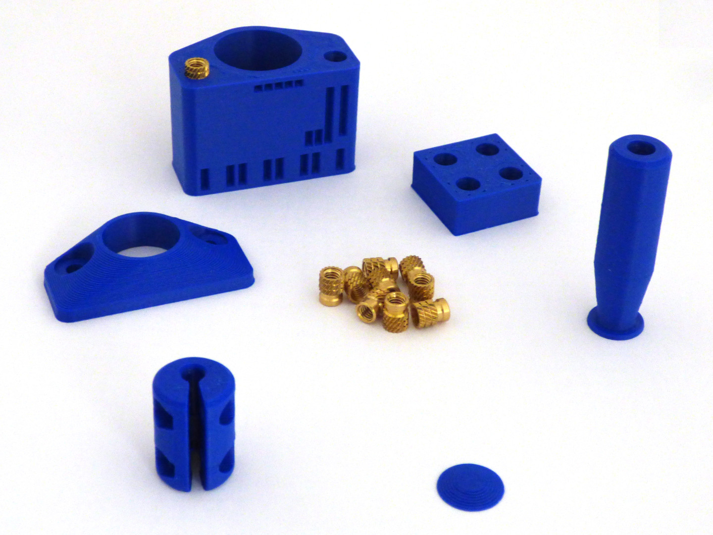
The openscad/ directory contains the .stl files for 3d-printing the mechanical part of the solder paste dispenser in ABS using FDM. These parts need finishing as follows:
- Take the workpiece insert_practice and place 4 heat-set inserts, as a test. Set your soldering iron to the filament extrusion temperature used during 3D printing, about 255°C.
- Take the workpiece motor_mount and place 4 heat-set inserts.
- Take the workpiece plunger and place 1 heat-set insert.
- Using a drop of acetone, glue the small conical plunger tip to the plunger. Acetone is a solvent for ABS.
Mechanical assembly is next.
 The mechanical part consists of stepper motor, coupler and leadscrew.
The stepper motor is a 28BYJ-48. The motor can be used "as is", or modified to bipolar for additional torque.
The leadscrew is 64mm of M4 threaded rod, 0.7mm pitch. The leadscrew mates with the M4 threaded insert in the plunger.
The coupler between motor and leadscrew is an Aluminum 4mm to 5mm shaft couplers, readily available from ebay or aliexpress. The all-metal construction easily handles the torque.
Attach the stepper motor to the motor mount using two nylon or stainless steel M4x10 hex socket screws. Nylon screws keep the weight down. Attach the syringe holder to the motor block with two M4x10 hex socket screws.
The syringe used is a BD 10cc "Luer-Lok", or one of its many oriental clones. Remove the black rubber piston head from the syringe and put it on the solder paste dispenser plunger.
Friction between rubber piston and syringe is what keeps the plunger from spinning. If during operation the plunger rotates instead of moving forward, clean the sides of the black rubber piston head with (isopropyl) alcohol to remove any grease.
 Align the pins of the PCB with the holes in the front of the motor mount. Fix the PCB in place with adhesive Velcro tape. Plug the OLED display in the connector marked "SDA SCK VCC GND". Connect the stepper motor to header J3.
Run 1-2m of cable from the 6-pin Dupont connector on the right of the PCB. The cable connects solder paste dispenser to a 5V TTL serial to USB converter (pins +5V,RX,TX,GND) and the foot switch (pins FTSW, GND).
If the motor turns the wrong way, swap pins A1 and A2, or pins B1 and B2.
At this point you have a working solder paste dispenser, ready for use.
For practice fill a syringe with a small amount (approx. 1 ml) of toothpaste. Print a pcb at scale 1:1 in black and white on paper and practice depositing toothpaste until you are comfortable with the solder paste dispenser.
Before filling the syringe, run a nylon wire inside the syringe body. A small piece of fishing line is suitable. This nylon wire creates a small leak in the seal between plunger and syringe body, allowing the air to escape while you push the plunger down. Once the plunger is down, simply pull the nylon wire out and you can begin dispensing.
-
There are a few situations which may result in breakage. If the piston pushes against the bottom of an empty syringe, something has to give. Likewise, if you try to squeeze paste out of a stoppered syringe. In general, avoid "unstoppable force meets inmovable object" situations. Something will break - the motor may tear itself off its mounts, for instance.
-
When not in use, loosen the syringe holder screws so the syringe isn't under constant pressure.
-
A solder paste dispenser is a small motor which pushes the plunger of a syringe. You can use it for solder paste or solder flux, but the dispenser can also be used as a syringe pump, to create small dots of glue in a precise and repeatable way, or to put small drops of lubricating oil on a mechanism.
-
The controller is not restricted to any specific model of solder paste dispenser; if a syringe pump uses a 5- or 6-wire unipolar or a 4-wire bipolar stepper motor, there's a reasonable chance this will work. Just check the stepper works at 5V and current stays below 1.2 amps.
-
FDM print settings: Increase perimeters on the pieces with heat-set inserts (motor_mount and plunger); this gives the heat-set inserts more material to grip onto.
-
Exactly how hard do we need to push? Take a syringe and (kitchen) scales. Grab the syringe by the syringe body, and push the syringe piston against the scales until the syringe releases solder paste. Take note of the weight the scales indicate. If the scales indicates pounds, multiply by 5 to get Newtons. If the scales indicate kilogrammes, multiply by 10 to get Newtons. Measured this way, pushing the plunger of 5cc and 10cc syringes of solder flux and solder paste needs a force between 20N and 30N.
-
The kicad pcb hardware design is under Creative Commons - Attribution Share Alike license.
-
This design was inspired by solder paste dispensers by zapta and geir. The mechanical part is a remix of zapta's, with only minor changes.
-
This design was built around a Atmega328p "Pro Mini" and a TB6612 stepper driver. An alternative design would be a STM32F103 "Black Pill" and a TMC2130 SilentStepStick stepper driver. The STM32F103 has enough cpu to run a comprehensive menu system and built-in usb. The TMC2130 stall detection allows detecting when the plunger has reached the bottom of the syringe, so software can move the plunger back a few steps before any mechanical damage occurs. But such a design would hit a different price point.


