Low power battery operated Sensors based on ESP8266 or ESP32, sending sensor data wireless using ESP-Now to an ESP8266/-32 Gateway connected to the Internet using WiFi (at the same time).
- Based on cheap standard ESP8266 (and ESP32) boards programmed in Arduino IDE
- 1+ year operation on 1200mAh or 18650 battery
- For-ever operation with a small solar panel (80x55mm)
- ESP-Now receiver (gateway) connected to WiFi/Internet - at same time
- Longer range than WiFi, no need for external antennas
- Battery and/or solar powered sensors and weather stations connected to home automations, to Blynk apps, to Thingspeak, MQTT, etc.
- Longer/safer reach and communication vs WiFi.
- Code template/demonstrator for ESP8266 and ESP32 Sensor node (sending on ESP-NOW)
- Code template/demonstrator for ESP8266 and ESP32 Gateway (receiving on ESP-NOW and providing a simple web server over WiFi),
Typical life time performance of a Sensor with ESP8266 LOLIN D1 Mini Pro V2.0.0 and temp sensor:
-
6+ months using a 1200mAh LiPo battery and SHT30 temp and humid sensor
-
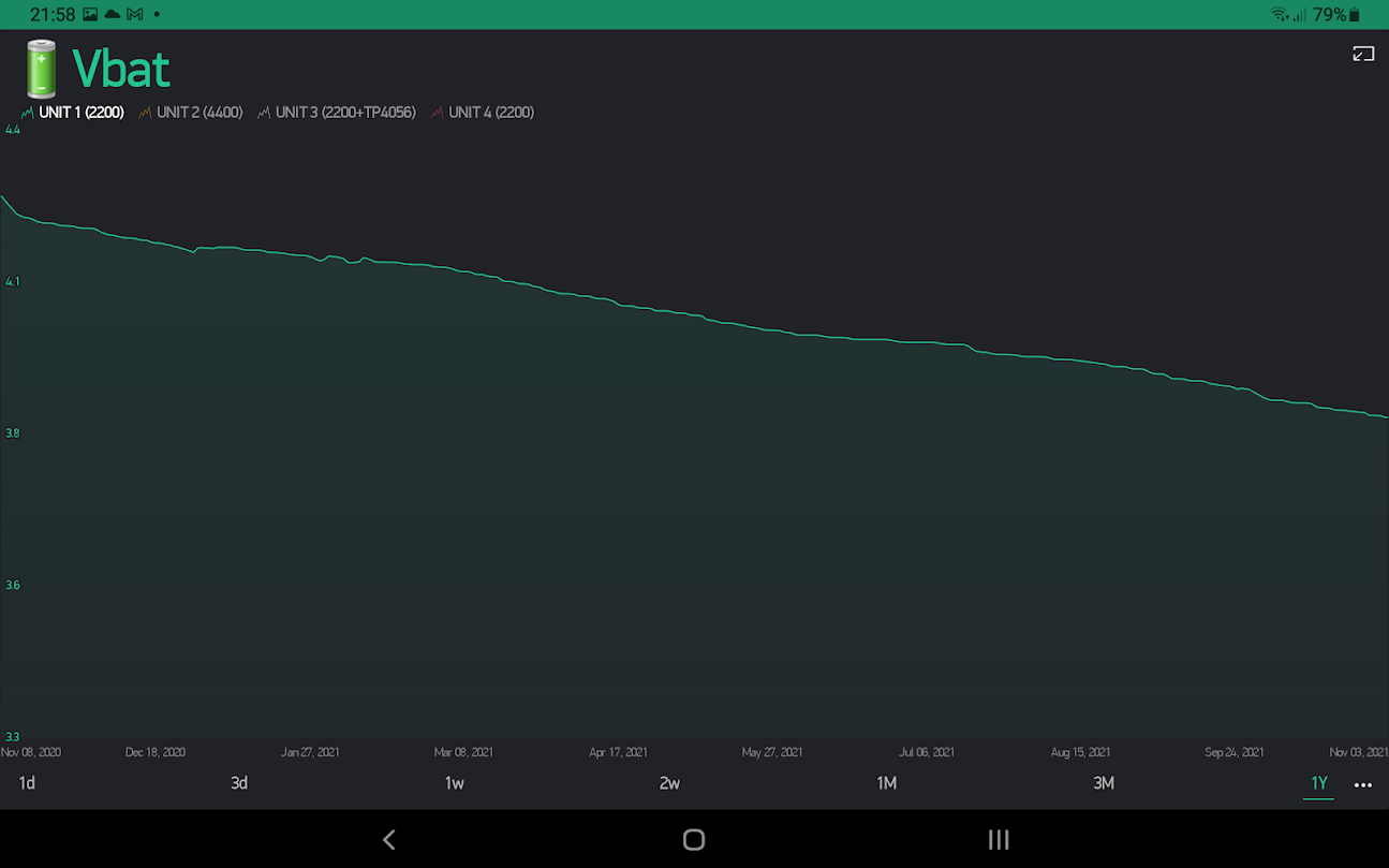
12+ months using a 2200mAh Li-Ion battery and SHT30
See graph. (Started 1+ month before start of graph. Still alive) https://raw.githubusercontent.com/jonasbystrom/ESP-Now-Sensor-system-with-WiFi/main/img/batlife_d1minipro_sht30_2200mah.png
-
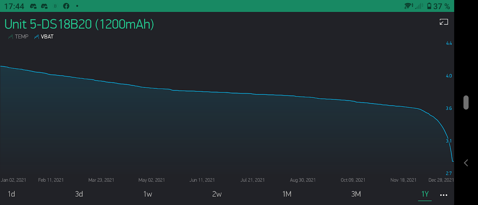
12+ months using a 1200mAh LiPo battery and DS18B20 temp sensor
See graph. (Started 1+ month before start of graph. Dead at end.) https://raw.githubusercontent.com/jonasbystrom/ESP-Now-Sensor-system-with-WiFi/main/img/batlife_d1minipro_ds18b20_1200mah.png
-
Continuous operation using a small 80x55mm 5v solar panel and a TP4056 charger with a 1200 or 2200 mAh battery.
-
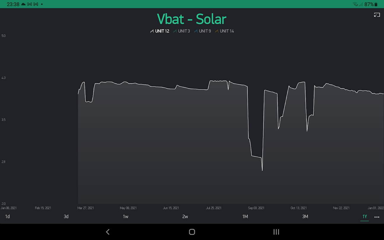
"Almost" continuous operation with a 45x45mm 5v solar panel, TP4056 and a small 500 mAh battery.
See graph. Some voltage drops are "problems" with humidity (i think). Anyway, it shows as small as 45x45mm solar panel and a small battery of 500 mAh is enough, even in dark winter time in Sweden (!). https://raw.githubusercontent.com/jonasbystrom/ESP-Now-Sensor-system-with-WiFi/main/img/batlife_d1minipro_sht30_45x45mm_solar_500mah.png
While HW is standard ESP boards, the sensor code is optimized for lowest power consumption possible. Sensors operate in Deep Sleep mode in 5 minute cycles. The WiFi module is active in the region of 60 ms per cycle.
The ESP-Now messages are "unnecessary" long and not just a few bytes as would be enough to send sensor data. However, I have standardized on a more general and longer format as the extra time to transmit a larger payload has quite a low impact on total energy consumption and battery lifetime.
The energy consumption can be divided into 3 classes:
-
Deep Sleep period: 300 secs, 50-200uA.
Note. Some boards draw much more than this in deep sleep.
-
Wake time, reading sensors and battery levels etc with WiFi OFF: 100-500ms, 15-30mA.
Fast sensors are preferred.
-
Wake time, sending data on ESP-Now with WiFi ON: 60ms, 70-150mA.
Fast, thanks to ESP-Now.
From the above typical values, it is realized the major energy consumption is in the Deep Sleep mode why it is important to use ESP boards with low deep sleep currents. The LOLIN D1 Mini Pro V2.0.0 is the standard ESP board with the longest battery lifetime I have tested.
Best sensor lifetime performance has been observed using a LOLIN SHT30 Temp and Humid sensor, with a modified driver library. The DS18B20 temp sensor comes very close by and sometimes even better, which probably is due to the chosen pull up resistor value. The BME280, draws a bit more current with a noticeable shorter lifetime. DHT11, DHT21 and DHT22 all consume more power, either by higher standby current or by longer reading times, resulting in shorter battery lifetime. They also produce much more false readings and easily gets over-saturated in humid outdoors conditions.
Note 1. I have a FireBeetle ESP8266 IoT Microcontroller board under test which looks very promising with potentially even longer battery performance.
Note 2. It would be further possible to reduce the deep sleep current by using ESP modules with no USB and LDO chips, or by disabling built-in LDO's replacing with more efficient external ones, etc. However, i haven't tried this very much but instead focused on an optimal SW solution using standard boards.

A gateway is a slave in ESP-Now terminology and receives sensor data sent to its MAC address. It can be implemented on ESP8266 or ESP32 with a minor code difference in the ESP-Now and WiFi API's.
WiFi and ESP-Now can be activated and operating at the same time. This allows one MCU to send the sensor data further using WiFi. This seems not to be commonly known. And is a bit tricky to get working. See source code how to.

A system comprise of up to 20 low power sensors and 1 gateway. Each sensor sends a unicast message every 5 minutes to the MAC-adress of the gateway. The gateway receives the messages and can process and send further over WiFi to any local or Internet service. The gateway can receive messages from sensors (on ESP-Now) and communicate over WiFi at the same time without any missed communications. Gateway connected to Blynk to display and monitor sensors is a good example which works very well.
A restriction is that the gateway must use the same WiFi channel on ESP-Now and WiFi. And due to some limitations in the ESP WiFi implementation, this only works on channel 1. (I have read articles saying it should be possible on also other channels, but I have only succeeded on channel 1.) This means the WiFi router must be set to channel 1 on the 2.4GHz band. It cannot be operated on "automatic channel".
There are some tricks involved during WiFi inits to get this working properly. See source code. (Maybe there are other tricks required to operate on any other channel than 1.)
It is possible, and preferred, to use a software defined MAC-address in the gateway instead of the default hardware MAC address. This allows for a replacement of the gateway hardware without any problems.
It is possible to run several systems in paralell. Just use a unique MAC address for each system. I am running 3 separate systems without any problems.
It is said ESP-Now has "3 times longer access range" than WiFi. I've never done any measurements, but I have noted long enough access range for my sensors in my installations.
Note. ESP-Now specification defines max 20 "peers" which is what i understand is "units to send to". A sensor in my system, sends to one (1) slave/gateway. However, there is no specification, what I know about, stating from how many controllers/sensors a slave/gateway can receive from. Maybe this number is larger than 20, and therefore would be possible to use more than 20 sensors per gateway. I have not tested this.


