![]()
![]()
![]()
 |
 |
 |
|---|---|---|
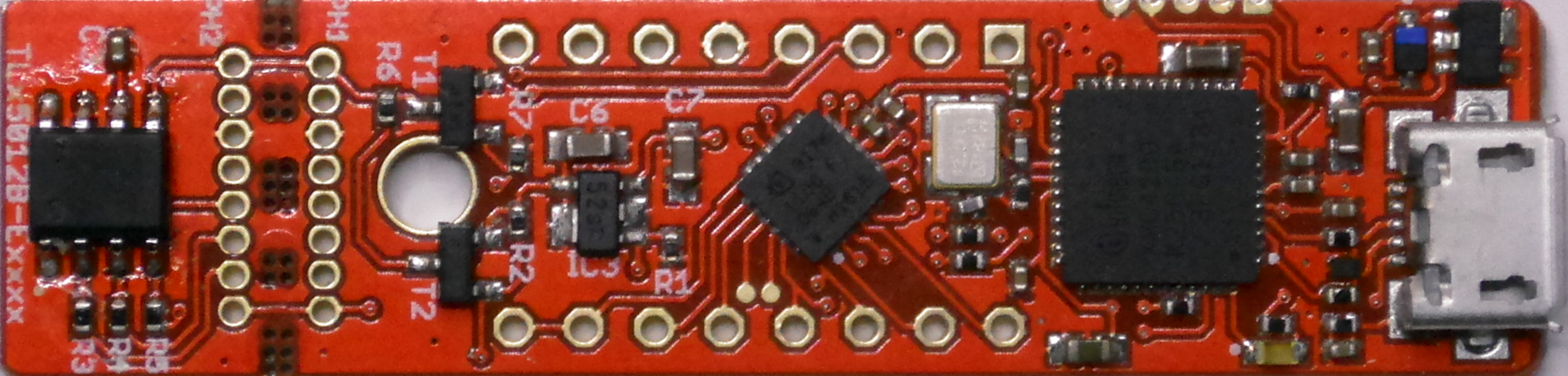
| bulk sensor | breakout board | Sensor2Go kit |
Library of Infineon's highly sensitive TLE5012B 360° magnetic angle sensor.
 |
||
| Arduino API | WICED API | TLE5012B API TLE5012B Register API |
| Getting Started | Getting Started | Porting Guide |
The TLE5012B is a 360° angle sensor that detects the orientation of a magnetic field. This is achieved by measuring sine and cosine angle components with monolithic integrated Giant Magneto Resistance (iGMR) elements. These raw signals (sine and cosine) are digitally processed internally to calculate the angle orientation of the magnetic field (magnet). The TLE5012B is a pre-calibrated sensor. The calibration parameters are stored in laser fuses. At start-up the values of the fuses are written into flip-flops, where these values can be changed by the application-specific parameters. Further precision of the angle measurement over a wide temperature range and a long lifetime can be improved by enabling an optional internal auto calibration algorithm. Data communications are accomplished with a bi-directional Synchronous Serial Communication (SSC) that is SPI-compatible. The sensor configuration is stored in registers, which are accessible by the SSC interface. Additionally four other interfaces are available with the TLE5012B: Pulse-Width-Modulation (PWM) Protocol, Short-PWM-Code (SPC) Protocol, Hall Switch Mode (HSM) and Incremental Interface (IIF). These interfaces can be used in parallel with SSC or alone. Pre-configured sensor derivate with different interface settings are available.
- Giant Magneto Resistance (GMR)-based principle
- Integrated magnetic field sensing for angle measurement
- 360° angle measurement with revolution counter and angle speed measurement
- Two separate highly accurate single bit SD-ADC
- 15 bit representation of absolute angle value on the output (resolution of 0.01°)
- 16 bit representation of sine / cosine values on the interface
- Max. 1.0° angle error over lifetime and temperature-range with activated auto-calibration
- Bi-directional SSC Interface up to 8 Mbit/s
- Interfaces: SSC, PWM, Incremental Interface (IIF), Hall Switch Mode (HSM), Short PWM Code (SPC, based on SENT protocol defined in SAE J2716)
- Output pins can be configured (programmed or pre-configured) as push-pull or open-drain
- Bus mode operation of multiple sensors on one line is possible with SSC or SPC interface
Please have a look at the wiki for all questions about this library and the sensor.
- Infineon Maker page
- Infineon Microcontroller
- Infineon XENSIV™ - Sensor 2GO kits
- Infineon Magnetic Sensor Kits
- TLE5012B variants
- TLE5012B manual
- GUI for Angle Sensor 2GO
- XMC-for-Arduino
- WICED Studio
- Cypress Evaluation Kit CYW43907AEVAL1F
This project is licensed under the MIT License - see the LICENSE file for details.


