Code Monkey home page Code Monkey logo

wemos-lora's Introduction

ESP8266 WeMos Shield for HopeRF RFM95 RFM96 RFM98 Lora Modules

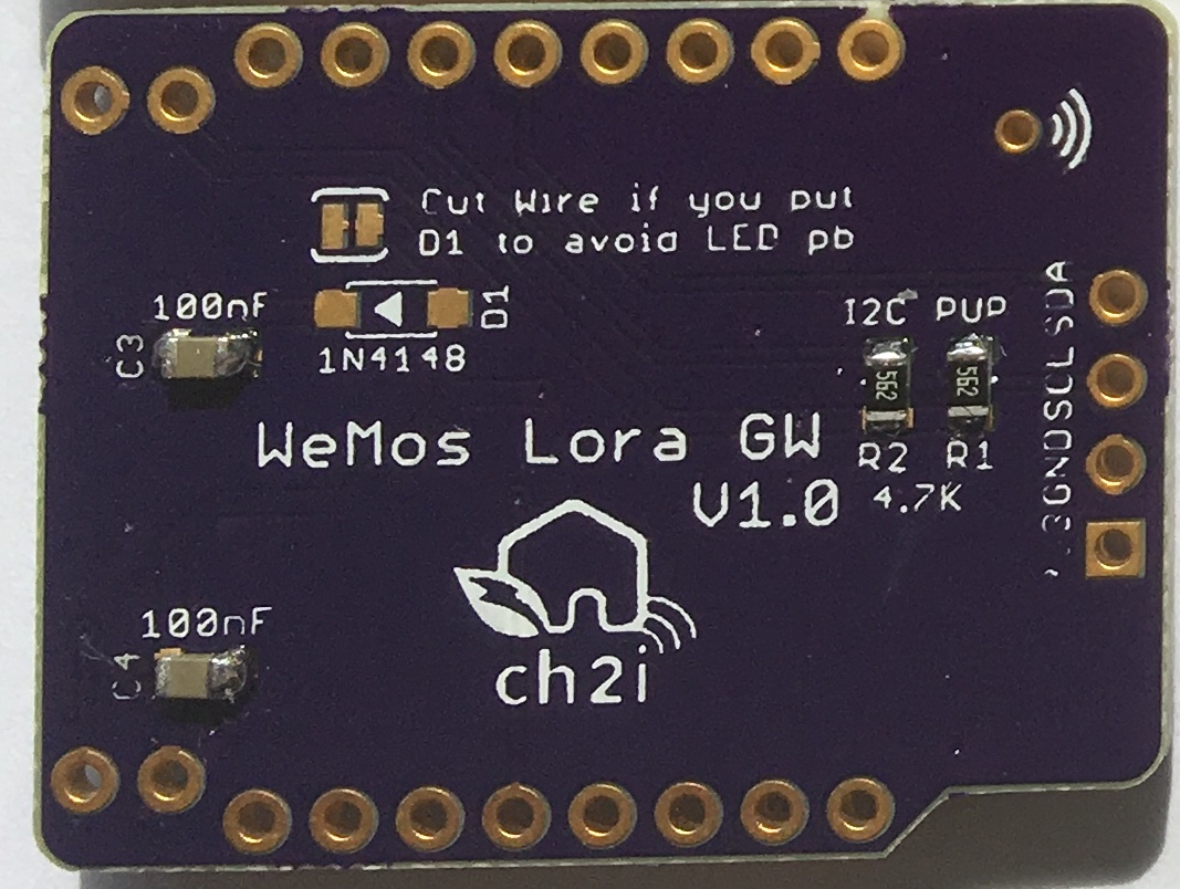
This shield is used to hold HopeRF Lora module Software with WeMos ESP8266 boards it has just few minimal features.

  • I2C Pullups placement
  • Classic I2C 128x64 OLED connector
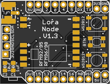
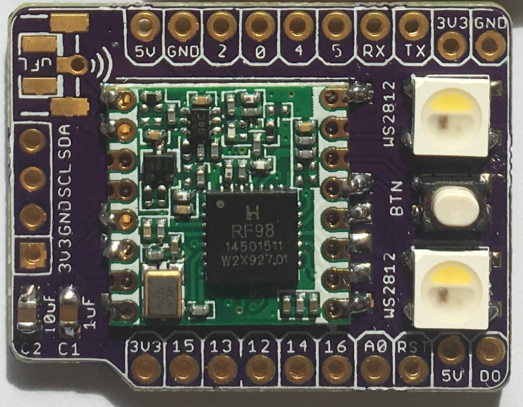
  • Placement for RFM95/96/98 Lora module
  • Placement for choosing single Wire, SMA or u-FL Antenna type
  • 2 x WS2812B Type LED for visual indication
  • Custom switch on GPIO2
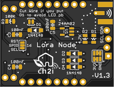
  • Added footprint for Microchip 24AA02E64 64 bits serial number (v1.1+)
  • Added Solder PAD jumper to be able to connect GPIO16 to Reset to enable deep sleep (V1.2+)

You can find more information on WeMos D1 mini boards (mini, mini pro, mini lite), it's really well documented. I now use WeMos boards instead of NodeMCU's one because they're just smaller, features remains the same, but I also suspect WeMos regulator far better quality than the one used on NodeMCU that are just fake of originals AMS117 3V3.

Boards arrived, I tested them, works fine with forked version of single Channel LoRaWAN Gateway but you can use any program that is compatible with RFM95 Lora module according it to real pinout.

Detailed Description

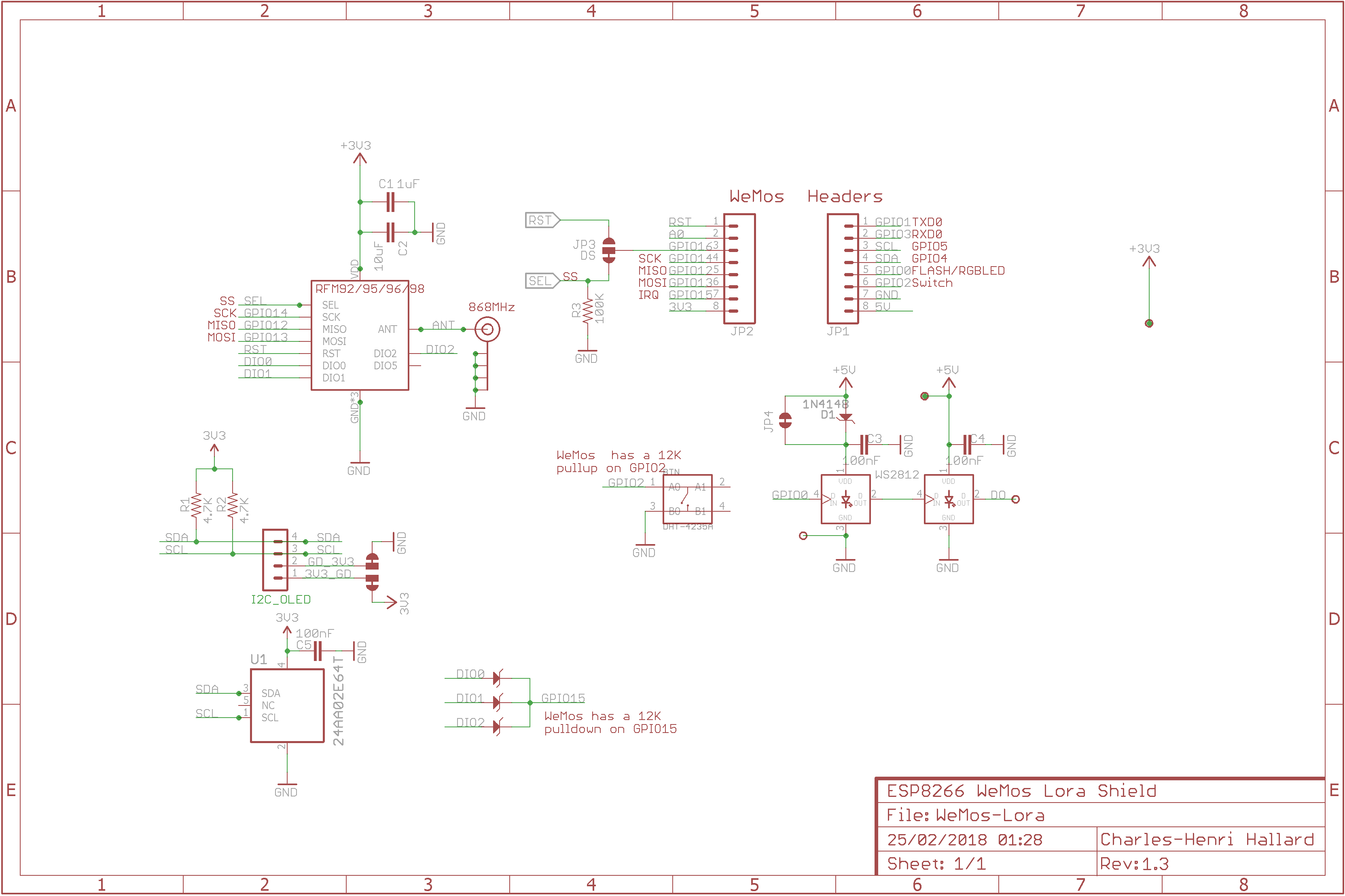
Look at the schematics for more informations.

SPI connexion is classic (MOSI/MISO/CLK),

New v1.3 Solder pad on bottom layer to be able to switch 3V3 and GND Pin. It's configured as old version mapping by default (silkscreen is correct).

Since V1.2, chip Select is still connected with GPIO16 by default but solder pad on bottom of the board allow you to connect GPIO16 to RESET for Deep Sleep. In this case:

  • add and solder R3 Pulldown (100K) to make RFM95 SPI device always selected
  • on bottom solder pad cut trace between GPIO19 and SEL
  • on bottom solder join GPIO16 and RST with solder

Other pins that may need be adapted into code (for example if you use TTN network gateway code) according to the following pinout

Please not that to avoid 3 GPIOs for DIO0,DIO1,DIO2 Interrupt, these 3 are OR'ed with 3 diodes, respectively named D2,D3 and D4. This permit to use only one IRQ pin (here GPIO15). This is only possible because on IRQ routine the RFM9x IRQ register is read and then software knows which one has been triggered. You can see more details ont this dedicated LMIC Pull Request

   WeMos D1          RFM9x Module
  GPIO12 (D6) <----> MISO
  GPIO13 (D7) <----> MOSI
  GPIO14 (D5) <----> CLK
  GPIO15 (D8) <----> DIO0/D2 OR DIO1/D3 OR DIO2/D4
  GPIO16 (D0) <----> SEL Chip Select (depending on bottom solder PAD position)

   WeMos D1         Shield Feature
  GPIO5  (D1) <----> I2C SCL
  GPIO4  (D2) <----> I2C SDA
  GPIO0  (D3) <----> WS2812 LEDS
  GPIO2  (D4) <----> Push Button
  GPIO16 (D0) <----> RESET (depending on bottom solder PAD position)

Schematic

schematic

Bill Of Material

Nothing fancy, all components are 0805 and/or PTH and can be ordered almost anywhere (digikey, mouser, radiospare, ...). use only what you need dependings on what you want to do. You can find lot of components on ebay or aliexpress, but since vendors are often ephemere, I put for reference the BOM on well known providers.

Here is the octopart BOM

Firmware

firmware

Boards

Topย  Bottom

You can order the PCB of this board at PCBs.io if you do so, PCBs.io give me discount that allow me to buy some new created boards.

Looks like PCBs.io is gone, I do not have any rewards from PCBs.io since August 2020 and my free order placed after are still not received, so my guess they are not on business anymore.

So you can order the board on oshpark. It's a pitty after several discuss with OSHPark that I can't have any rewards for each people ordering my boards, this would allow me to order free PCB for shared projects and create new ones. For information my shared boards generated a total of $285 162.00 orders at PCBs.io in 4 years, not bad at all :-)

Hoping one day OSHparks will thanks me giving them this market.

Assembled boards (V1.0)

Top

Bottom

License

Creative Commons Attribution-NonCommercial 4.0

This work is licensed under a Creative Commons Attribution-NonCommercial 4.0 International License
If you want to do commercial stuff with this project, please contact CH2i company so we can organize an simple agreement.

Misc

See news and other projects on my blog

wemos-lora's People

Contributors

hallard avatar

Stargazers

 avatar  avatar  avatar  avatar  avatar  avatar  avatar  avatar  avatar  avatar  avatar  avatar  avatar  avatar  avatar  avatar  avatar  avatar  avatar  avatar  avatar  avatar  avatar  avatar  avatar  avatar  avatar  avatar  avatar  avatar  avatar  avatar  avatar  avatar  avatar  avatar  avatar  avatar  avatar  avatar  avatar  avatar  avatar  avatar  avatar  avatar  avatar  avatar  avatar  avatar  avatar  avatar  avatar  avatar  avatar  avatar  avatar  avatar  avatar  avatar  avatar  avatar  avatar  avatar  avatar  avatar  avatar  avatar  avatar  avatar  avatar  avatar  avatar  avatar  avatar  avatar  avatar  avatar  avatar  avatar  avatar  avatar  avatar  avatar  avatar  avatar  avatar  avatar  avatar  avatar  avatar  avatar  avatar  avatar  avatar  avatar  avatar  avatar  avatar  avatar

Watchers

 avatar  avatar  avatar  avatar  avatar  avatar  avatar  avatar  avatar  avatar  avatar  avatar  avatar  avatar  avatar  avatar  avatar  avatar  avatar  avatar  avatar  avatar  avatar  avatar  avatar  avatar  avatar  avatar  avatar  avatar  avatar  avatar  avatar  avatar  avatar  avatar  avatar  avatar  avatar  avatar  avatar  avatar  avatar  avatar  avatar  avatar  avatar  avatar

wemos-lora's Issues

SMD component list

Hi, could you provide the SMD component list ( with dimensions) ?
Thanks.

Screen Print Error?

Thanks for this great board.
I made some problems for myself following the screen print. The board matches the circuit diagram with NSS connected to GPIO16. The Detail Description is also clear. I think RST and SEL are labelled incorrectly.

SSD1306 Header Alignment

Hi

In the 1.1 version the pins for the display on the board edge are out of alignment. The png image you have of the board in the repository also reflects this.

Thanks

Tim

OLED module PINs

The order seems a bit weird, 99% of the cheap modules have the pin in the order

GND Vcc SCL SDA

and not

Vcc GND SCL SDA

as on the your PCB

Pullup resistors on I2C, why?

Hi, is there a motive for R1 and R2 (pullup resistors for SDA and SCL)?
I'd like to use Wemos pins D1 and D2 for a SoftwareSerial...
Thanks

BOM missing antenna connector

Any advice on the type of antenna connector to put on the PCB? I noticed the BOM is missing that info.

I would love to use a SMA or u.fl type antenna, but don't know of a connector that fits that footprint on the PCB.

Multiplexing made easier

Hi,

I have been implementing the dio0,dio1,dio2 pin multiplexing in my single channel gateway using your excellent PCB.

When doing the same in regular LoRa node using your code I just wondered why you do not use the lmic_pin list. If dio[0]==dio[1] one would assume that you are multplexing the pins for a ESP8266 which will make the code really simple.

Maarten

PS. Something like

static void hal_io_check() {
uint8_t i;
// If two DIO pins are equal, we assume pin multiplexing
if (lmic_pins.dio[0]==lmic_pins.dio[1])
{
// Check IRQ flags in radio module
if ( radio_has_irq() )
radio_irq_handler(0);
}
//
else {
for (i = 0; i < NUM_DIO; ++i) {
if (lmic_pins.dio[i] == LMIC_UNUSED_PIN)
continue;

    if (dio_states[i] != digitalRead(lmic_pins.dio[i])) {
        dio_states[i] = !dio_states[i];
        if (dio_states[i])
            radio_irq_handler(i);
    }
}

}
}

RFM95 disturbes D1 Mini

Hi, a friend had a lot of issues to send LORA frames (not lorawan). The rfm-pcb and the d1 mini are stacked. When he send frames, the usb communication is e. g. corrupted.

After a lot of try&error he recognized, that a reduction of the transmission power fix this issue.
Or using 15cm jumper wire also works.

Do you also observed this issues or have any advice for us.

Thx.

Klaus

Unable to use deep sleep

I am running a LMIC implementation using this shield. This works fine, but the choice of using GPIO16 for SS breaks the possibility to use the timed deep sleep feature of the ESP8266. In order to make timed deep sleep work you have to connect GPIO16 to the ESP's RST pin. When using this shield, the board won't start up properly when connecting GPIO16 to RST. Maybe, in the next version, the GPIO16 pin can be used for an optional feature so there will be a way to use timed deep sleep.
Especially for battery powered LoraWan nodes a lot of power can be preserved by using deep sleep.

DIO0 GPIO15 boot fail

Hi, i have an issue, the gateway works perfectly fine but i have a small problem, i have the gpio15 pulled down to ground with a 10k resistor, but if i connect the 1n4148 diode for dio0 on gpio15 the esp12e will not boot. If i leave the diode disconnected, power up the board and only then connect the diode on gpio15 it works like a charm, any idea about the reason ?

Thanks a lot

Does 1.1 version work?

Hi ,
I recently ordered the board from pcbs.io but so far haven't been able to get it working.
Tried it with your LMIC fork version both with and with out the diodes.
Has any one been able to successfully run it with 1.1 version boards.
Wemos keeps crashing right after serial.begin.
Also with the sheild attached I cant upload updated skeptch any more from arduino IDE, works ok if I take out the shield.

Thanks

Bill of materials

Please add a list of components needed to populate this board. I was unaware that I needed 3 diodes to get it in a usable state. I am also still unsure which exact component the diodes should be. Are they 0805?

  • Number (ex. D1, R3)
  • Value (ex. 1N4148, 10K)
  • Footprint/size (ex. 0805)
  • A link to a source for the component

gateway and/or node

hi,
it 's not very clear for me : is is a gateway ? or just a lora node ? or the both ?
thanks for your big and interesting work

Correct Pins?

I know this project is old, but it seems the hardware should still be usable. I am trying to make a LoRa transmitter using the LoRa library in the Arduino IDE. I am converting code I was running on a Heltec ESP32 LoRa board. I am trying to follow this (https://github.com/SensorsIot/LoRa-Point-to-Point) which uses this board. I'm not sure if the board has been assembled correctly, but I think it has. Both the leds and oled are working, but I know they are not part of the LoRa portion.

In the sample code, it uses this command to configure the pins:
LoRa.setPins(16, 17, 15); // set CS, reset, IRQ pin
It compiles and runs, but the receiver I have is not seeing anything. They are both on the same frequency and SF.

Any suggestions on what might not be right?

EDIT: I am seeing it get a package every once in awhile, so I guess it is transmitting, but most of the packets aren't being received.

Older Versions

I appear to have a quantity of older "Lora Node Mini" boards for Wemos D1 mini. I bought them about 2 years ago. They do not have a version number or CH21 logo but have the number WS2812 screened just under the RFM9x moduls pads. The layout and parts placement is identical to V1.3 sans the extra features.
So, Question is: Is this indeed an early version of WeMos-Lora and is is usable?
Thanks much Peter

OLED Pins misalignment

In v1.3 the holes for the OLED pins are misaligned. The center hole seems flipped and does not align perfectly with the other two PINs. This makes it hard to just "plug and play" a standard breadboard-friendly OLED screen.

Is there any reason for this layout?

wemos-lora-bot

Recommend Projects

  • React photo React

    A declarative, efficient, and flexible JavaScript library for building user interfaces.

  • Vue.js photo Vue.js

    ๐Ÿ–– Vue.js is a progressive, incrementally-adoptable JavaScript framework for building UI on the web.

  • Typescript photo Typescript

    TypeScript is a superset of JavaScript that compiles to clean JavaScript output.

  • TensorFlow photo TensorFlow

    An Open Source Machine Learning Framework for Everyone

  • Django photo Django

    The Web framework for perfectionists with deadlines.

  • D3 photo D3

    Bring data to life with SVG, Canvas and HTML. ๐Ÿ“Š๐Ÿ“ˆ๐ŸŽ‰

Recommend Topics

  • javascript

    JavaScript (JS) is a lightweight interpreted programming language with first-class functions.

  • web

    Some thing interesting about web. New door for the world.

  • server

    A server is a program made to process requests and deliver data to clients.

  • Machine learning

    Machine learning is a way of modeling and interpreting data that allows a piece of software to respond intelligently.

  • Game

    Some thing interesting about game, make everyone happy.

Recommend Org

  • Facebook photo Facebook

    We are working to build community through open source technology. NB: members must have two-factor auth.

  • Microsoft photo Microsoft

    Open source projects and samples from Microsoft.

  • Google photo Google

    Google โค๏ธ Open Source for everyone.

  • D3 photo D3

    Data-Driven Documents codes.