- Implement lenet using HLS to explore tradeoff of micro-architecture designs vs. area/performance.
- Port the lenet acclerator to RISC-V virtual platform.
- Implement multi CPU-Lenet PE pairs (ranges from 1 to 4 CPU-PE pairs) and its corresponding multi thread program.
- Implement a status register in the lenet acclerator and dma that notifies if the current work is done or not to the software through interrupt.
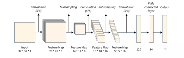
In this project, the lenet model was selected as the application to implement its hardware using HLS and port the lenet acclerator to RISC-V Virtual Platform. The following picture shows the architecture of the lenet model, which contains two convolution layers, two max-pooling layers, and three fully connected layers.
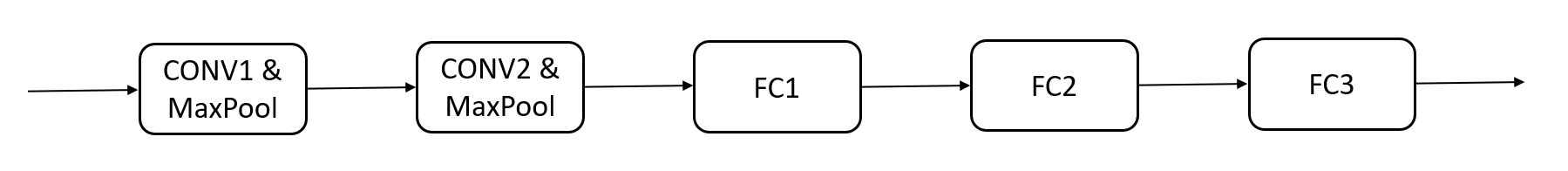
In the implementation of the lenet acclerator, I used 8-bit quantized input values and weights to infer the model. In addition, convolution layer and max-pooling layer are fused to reduce buffer size, as shown in the picture below.
The following diagram shows the implementation of hardware architecture of the lenet acclerator. Since the weights of the model are pretrained constant, they can be implemented as ROMs. The input activations and output activations will be stored in activation SRAM.
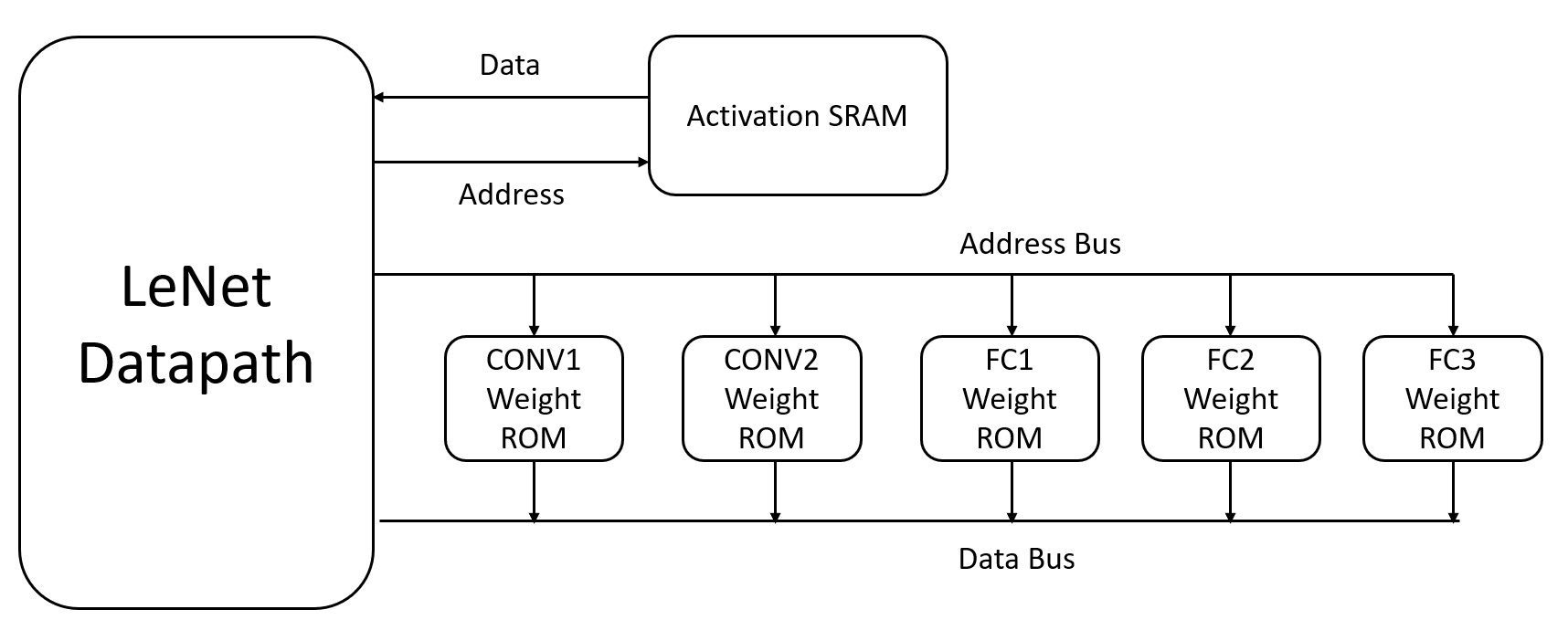
In addition, a double buffer was introduced to achieve higher parallelism and to reduce the size of the activation SRAM. Since the internal output activations are not needed in the end, we only need the output of the last layer, so the double buffer works effectively.
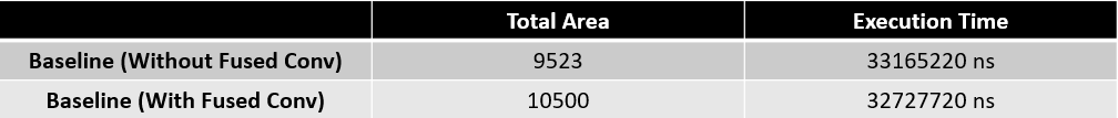
The following diagram shows the performance of the baseline implementation of the LeNet accelerator using HLS. "Baseline (Without Fused Conv)" represents the result of the LeNet CNN network, while "Baseline (With Fused Conv)" represents the result after fusing the convolutional layer with the max-pooling layer. Both the area and performance are quite similar.
The following code section shows the implementation of fully connected layers with tiling (only FC1 is demonstrated, but other FC layers are implemented using same method). Different numbers of PEs are used to balance performance and area.
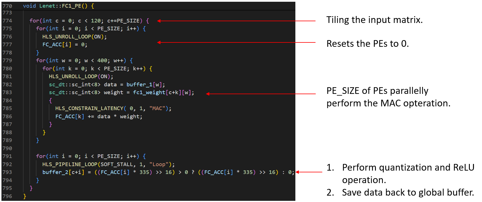
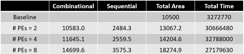
The following diagram shows the area and performance using different numbers of PEs. As the number of PEs increases, performance improvs, but area also increases. Compared to the baseline implementation, using 8 PEs achieves 1.2x speedup.
The following code section shows the implementation of fully connected layers with different loop piepelining strategies and loop unrolling (only FC1 is demonstrated, but the other FC layers are implemented using same method). Different loop pipeline and loop unroll strategies are used to balance performance and area.
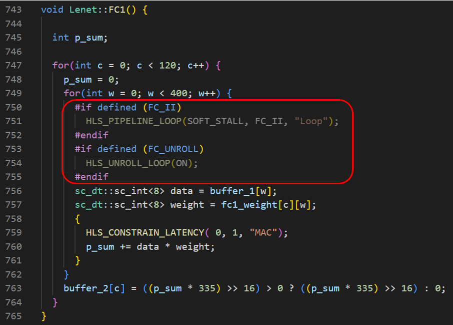
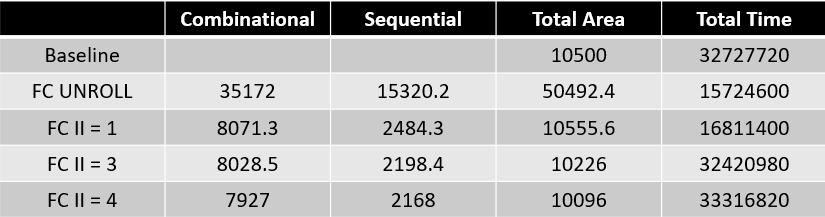
The following diagram shows the area and performance using different loop pipeline and loop unroll strategies in fully connected layers. When using loop pipeline with II set to 1 in the fully connected layers, the overall hardware can achieve a speedup of 1.94 times compared to the baseline, with only a slight increase in the total area.
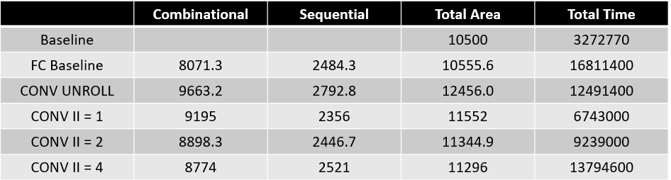
The convolutional layers are implemented using different loop pipelining strategies and loop unrolling, based on setting the fully connected layer loop pipeline II to 1. Different loop pipelining and loop unrolling strategies are used in the convolutional layers to balance performance and area. When using loop pipeline with II set to 1 in the fully connected layers and II set to 1 in the convolution layers, the overall hardware can achieve a speedup of 4.85 times compared to the baseline, with only a slight increase in the total area.
In the implementation of double buffered, I've also tried to seperate dobule buffer into four buffers to achieve more parallelism. However, the performance does not improve that much.
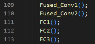
The following figure shows the implementation of original implementation using double buffer. In this implementation, parallelism could not be achieved across layers. The performance and area of this implementation is shown in the diagram as v1.
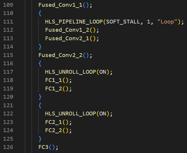
The following figure shows the implementation using four buffers. Each layer is partitioned into two parts. Parallelism is implemented between the first convolution and the second convolution. Additionally, the fully connected layers are partitioned into two parts to infer in parallel. The performance and area of this implementation is shown in the diagram as v2.
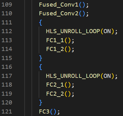
The following figure shows another implementation using four buffers. Each layer is partitioned into two parts. Parallelism is implemented in the fully connected layers, which are partitioned into two parts to infer in parallel. The performance and area of this implementation is shown in the diagram as v3.
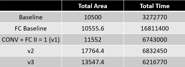
The following diagram shows area and performance of v1, v2, and v3 implementation.
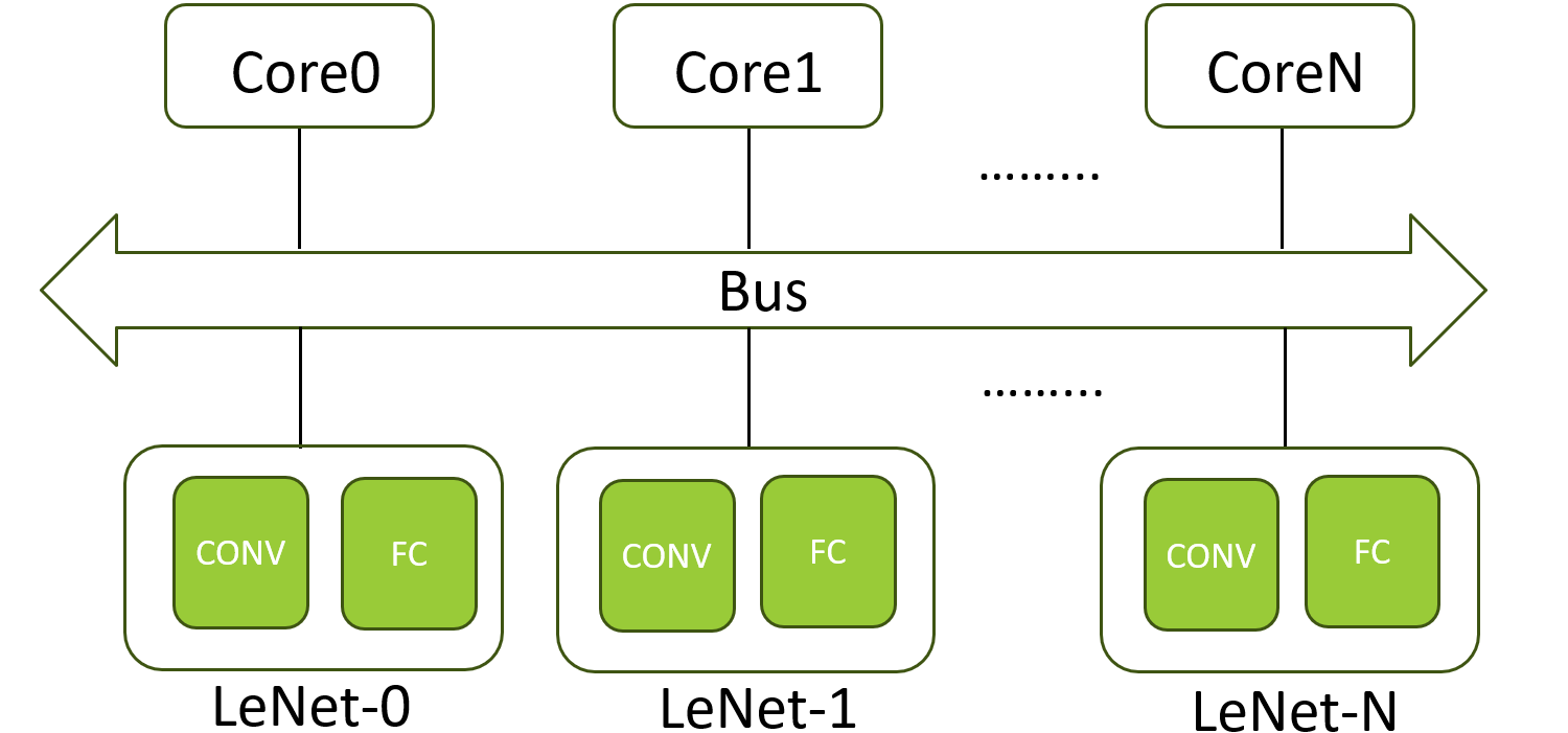
The following block diagram shows the architecture of virtual platform. The CPU-LeNet PEs pairs range from 1 CPU-PE pair to 4 CPU-PEs pair. In addition, the CPU-LeNet PEs pairs are controlled using multi-thread software implementation.
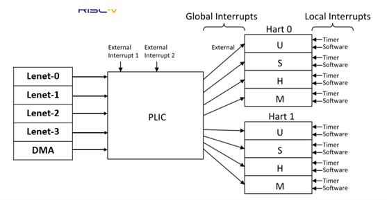
- The Platform Level Interrupt Controller (PLIC) is used to handle interrupts from the DMA (when the DMA transfer is complete) and from the LeNet Datapath (when the LeNet calculation is complete).
- The timer interrupt is used to calulate the num ticks of the programs.
The following code section shows that the program will wait until the accelerator finishes. After the accelerator completes its computation, it will send an interrupt to the program, which will be handled by the interrupt callback handler. To achieve this mechanism, the interrupt callback handler will be registered when the program starts.
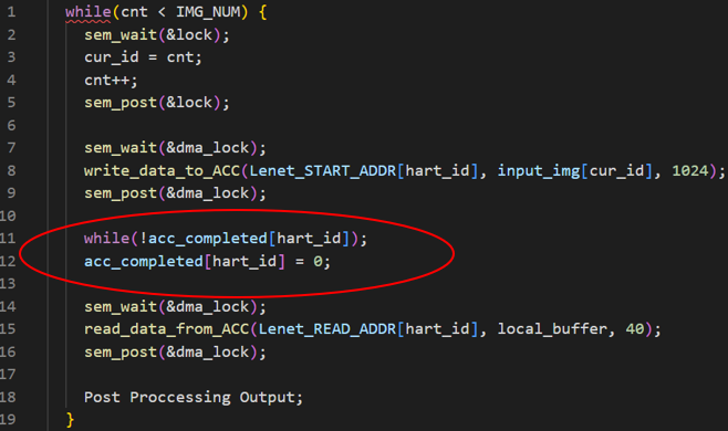
The following code section shows the implementation of multi-thread pseudocode to controll multiple CPU-PE pairs. First of all, each CPU will dynamically to get the current processing image ID in the critical section. Then, the CPUs will transfer the image to be inferred using DMA. After that, the lenet acclerator will start to compute. Once the Lenet accelerator completes, it will send an interrupt to the platform-level interrupt controller (PLIC). The interrupt callback handler will then set acc_completed[hart_id] to 1. At this point, we can read the result from the Lenet accelerator through DMA controller.
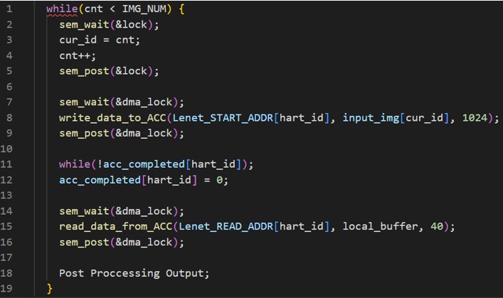
The DMA transaction can be modeled as initial cycle + (sent data in bytes/DMA bandwidth). Assuming initial cycle is 2. In the implementaion, the DMA bandwidth is 64 bytes/cycle and the input data is 1024 bytes. Thus, the DMA transaction is calculated as initial cycle + (sent data in bytes/DMA bandwidth) = 2 + 1024/64.
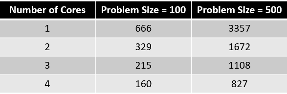
The following diagram shows the performance (in term of number of ticks) of different problem sizes with different number of cores.
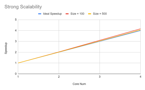
The following diagram demonstrates the strong scalability of the system. Since interconnects are not considered at this point, we can achieve ideal speedup. However, if interconnects are considered, the speedup plot might saturate as the number of cores increases.
- RISC-V Interrupt Hadler : https://ithelp.ithome.com.tw/m/articles/10291055
