Code Monkey home page Code Monkey logo

woodworking's Introduction

Description

FreeCAD is great software. This workbench extends the features of FreeCAD for Woodworking. The main goal for this workbench is to make the furniture designing process in FreeCAD simpler.

intro

Release notes

New significant changes since the last stable version:

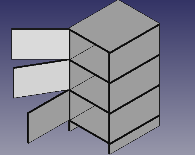
  • tenon option at magicDowels tool
  • getDimensions engine improved

Installation

Step 0. Install correct FreeCAD version:

Step 1. Get FreeCAD Mod folder localization:

  • From FreeCAD python console run command:

      FreeCAD.ConfigDump()["UserAppData"]
    
  • If there is no Mod folder, create it.

Step 2. Install Woodworking workbench:

  • Go to FreeCAD Mod directory, for example, in Xubuntu operating system:

      cd  ~/.local/share/FreeCAD/Mod/
    
  • Get the latest Woodworking workbench repository:

      git clone https://github.com/dprojects/Woodworking.git
    

Step 2. Installation in other operating systems:

  • Download and unpack Woodworking repository.
  • Copy the folder Woodworking to the FreeCAD module directory (Mod folder).

Note: You can update this workbench later via debuginfo tool.

Certified platforms

  • Stable certified versions download at: Woodworking/releases

  • For cutting edge features download: the master branch

  • Current development platform:

      OS: Ubuntu 22.04.3 LTS (XFCE/xubuntu)
      Word size of FreeCAD: 64-bit
      Version: 0.21.2.33771 (Git) AppImage
      Build type: Release
      Branch: (HEAD detached at 0.21.2)
      Hash: b9bfa5c5507506e4515816414cd27f4851d00489
      Python 3.10.13, Qt 5.15.8, Coin 4.0.0, Vtk 9.2.6, OCC 7.6.3
      Locale: English/United States (en_US)
      Installed mods: 
      * Woodworking 0.21.2.33771
    

Note:

  • I don't have Windows or macOS, so I am not able to test and certify this workbench for those systems. However, if you use FreeCAD AppImage there is a good chance this will be working correctly.
  • To get better stability make sure your current Woodworking workbench version has always the same version number as the FreeCAD version. You can also verify this via debuginfo tool.

Known issues

  • Issue: Cut-list, BOM, report toPrint is not in the center of the page.
    • Workaround: FreeCAD 0.21.2 has bug related to the TechDraw template. The TechDraw template size is always zero, so the center of the page cannot be calculated correctly. If this is issue for you, can adjust the report manually or please try higher FreeCAD version with this bug fixed (0.22).

Extras

This woodworking workbench is delivered with several useful extras:

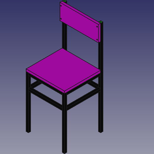
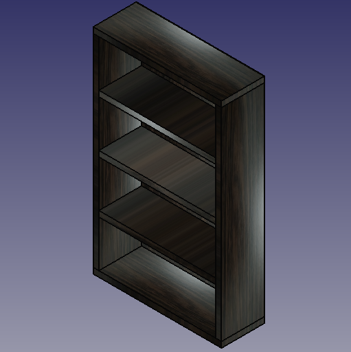
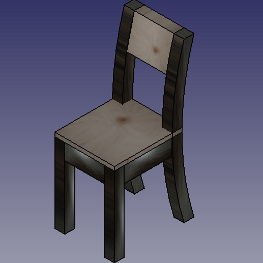
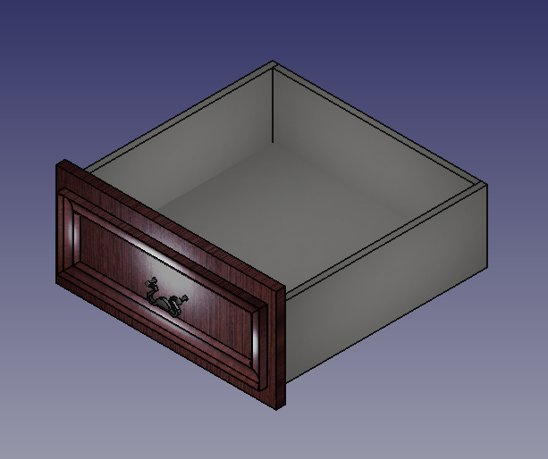
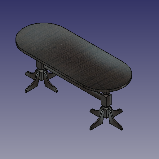
  • Fully parametric examples - this folder inside woodworking workbench contains sample furniture projects. All of the furniture examples are parametric. So, you can quickly adopt it to your current project, without designing e.g. bookcase from scratch. You can also add decoration, if needed, or even merge with other projects.
  • Fixture examples - this is new approach to 3D modeling. For example you can replace any Cylinder with realistic looking detailed screw. This is very powerful feature and gives a lot of flexibility and simplifies the process of making model detailed.
  • Texture samples - sample textures for woodworking projects purposes.

API for developers

The Woodworking workbench also has an API for developers. This library contains functions that solve the Topology Naming Problem. You can also leaglly create your own tools and extend the workbench in your private repository in accordance with the MIT license:

Note:

  • If you have Woodowrking workbench installed you don't have to install the MagicPanels library manaually. Also you can view the library directly from Woodworking workbench via: scanObjects tool.
  • For programming I use simple Krusader with F4 KWrite editor. I have set tabulators as indent: Settings -> Configure Editor -> Editing -> Indentation -> Tabulators -> Tab width: 4 characters.

Translations

For Woodworking workbench translation see dedicated directory: translations

License

MIT for all Woodworking workbench content.

Contact

c1r1 c2r1
c1r2 c2r2
c1r3 c2r3
c1r4 c2r4

woodworking's People

Contributors

dprojects avatar

Stargazers

 avatar  avatar  avatar  avatar  avatar  avatar  avatar  avatar  avatar  avatar  avatar  avatar  avatar  avatar  avatar  avatar  avatar  avatar  avatar  avatar  avatar  avatar  avatar  avatar  avatar  avatar  avatar  avatar  avatar  avatar  avatar  avatar  avatar  avatar  avatar  avatar  avatar  avatar  avatar  avatar  avatar  avatar  avatar  avatar  avatar  avatar  avatar  avatar  avatar  avatar  avatar  avatar  avatar  avatar  avatar  avatar  avatar  avatar  avatar  avatar  avatar  avatar  avatar  avatar  avatar  avatar  avatar  avatar  avatar  avatar  avatar  avatar  avatar  avatar  avatar  avatar  avatar  avatar  avatar  avatar  avatar  avatar  avatar  avatar  avatar  avatar  avatar  avatar  avatar  avatar  avatar  avatar  avatar  avatar  avatar  avatar  avatar  avatar  avatar  avatar

Watchers

 avatar  avatar  avatar  avatar  avatar  avatar  avatar  avatar  avatar

woodworking's Issues

A question about cutting shape from part

I want to create a panel with a 45 degree cut on one edge to use on a French Cleat wall. I've tried for an hour, but I can't figure it out. I built the panel using your workbench. Do I need a tool from another workbench? Should I make the part in the part or part design workbench and attach it using your workbench? Any help is appreciated.

Latest release workbench incompatible with latest release FreeCAD

As a consequence of issue #33, it was necessary to install the "Latest release" (0.20) from GitHub manually. This version is incompatible with the latest release of FreeCAD (0.21). After install the Anchor icon is missing. There may be other undiscovered incompatibilities.

I'm not sure what the answer is here, but the workbench "latest release" should be compatible with FreeCAD latest release. The install mentioned in issue #33 was attempting to install workbench 0.21, so fixing #33 will resolve this problem.

Workbench does not appear in FreeCAD drop-down list

Woodworking does not appear in the drop-down workbench list. Same results with View--> Workbenches. It also does not appear in the Addon Manager. Could you help me debug it? I've used FreeCAD a few times, but I am no expert. I've rebuilt FreeCAD because I had the same issue with the older (approx 1 year old) version.


Below are the steps of installation of the workbench:

I checked the location of the AppData with
FreeCAD.ConfigDump()["UserAppData"]

zoltan@adrian ~/.local/share/FreeCAD $   git clone https://github.com/dprojects/Woodworking.git
Cloning into 'Woodworking'...
remote: Enumerating objects: 2393, done.
remote: Counting objects: 100% (142/142), done.
remote: Compressing objects: 100% (104/104), done.
remote: Total 2393 (delta 86), reused 80 (delta 38), pack-reused 2251
Receiving objects: 100% (2393/2393), 72.51 MiB | 11.16 MiB/s, done.
Resolving deltas: 100% (1376/1376), done.
OS: Manjaro Linux (KDE/plasma)
Word size of FreeCAD: 64-bit
Version: 0.20.2.29603 (Git)
Build type: Release
Branch: makepkg
Hash: 930dd9a76203a3260b1e6256c70c1c3cad8c5cb8
Python 3.10.9, Qt 5.15.8, Coin 4.0.1, Vtk 9.2.6, OCC 7.6.3
Locale: English/United States (en_US)
Installed mods: 
  * fasteners 0.4.56
  * CADExchanger
  * lattice2 1.0.0
  * DynamicData 2.46.0
  * OpticsWorkbench 1.0.9
  * LCInterlocking
  * Assembly4 0.50.2
  * ExplodedAssembly
  * Estimate 0.1.2
  * parts_library

If you cut a panel, it won't show up in the cut list without the base panel being shown

Love the workbench! Makes my life much easier.

If you use the cut list with the visible objects option turned on so only visible objects show in the cut list, cut objects don't show up in the cut list if the base panel isn't visible.

For example, I create a panel and a dowel. If I cut the panel with the dowel, the panel and the dowel are no longer visible. I then use cut list and choose to only show visible objects, that cut object doesn't show in the cut list.

I've got a project with panels with tons of cuts, I'd have to go and make all the base panels visible in order for them to show up in the cut list. If you could show the panel dimensions if the parent cut object is visible, that'd be helpful.

Thanks!

magicMove error

I'm trying to use the magicMove tool, but I'm getting an error:

'Gui.View3DInventor' object has no attribute 'getCornerCrossSize'Running the Python command 'magicMove' failed:
Traceback (most recent call last):
  File "/home/maximus/.FreeCAD/Mod/woodworking/loadTools.py", line 353, in Activated
    __import__(module, globals(), locals(), [], 0)
  File "/tmp/.mount_FreeCAawP184/usr/lib/python3.10/site-packages/shiboken2/files.dir/shibokensupport/feature.py", line 139, in _import
    return original_import(name, *args, **kwargs)
  File "/home/maximus/.FreeCAD/Mod/woodworking/Tools/MagicPanels/magicMove.py", line 1023, in <module>
    showQtGUI()
  File "/home/maximus/.FreeCAD/Mod/woodworking/Tools/MagicPanels/magicMove.py", line 16, in showQtGUI
    class QtMainClass(QtGui.QDialog):
  File "/home/maximus/.FreeCAD/Mod/woodworking/Tools/MagicPanels/magicMove.py", line 65, in QtMainClass
    gCrossCorner = FreeCADGui.ActiveDocument.ActiveView.getCornerCrossSize()

'Gui.View3DInventor' object has no attribute 'getCornerCrossSize'

Word size of FreeCAD: 64-bit
Version: 2023.131.26244 +5365 (Git) AppImage
Build type: Release
Branch: LinkDaily
Hash: 73c4ca254c5de8849d104973482e98399fb24863
Python version: 3.10.8
Qt version: 5.15.4
Coin version: 4.0.1
OCC version: 7.6.3

documentation

Hi,
The English documentation is very hard to read. While I am willing to fix it a little bit, I don't have the time to actually to write the documentation. (I was a technical writer once upon a time)
I also never used any CAD programs before and I and I don't see any definition of terms. Youe youtube demos have no talking explaining what you are doing, so they offer me limited help.
I'm,sure that if I had some background using CAD programs I would probably understand where to start. I want to design a workbench using freecad and your workbench, but I have no idea how do it with freecad and your workbench. Also how do I set up the woodworking workbench to use inches and feet instead of metric.
Are you help files written in HTML or Markdown? thanks,
Aaron
[email protected]

Typos found in source

./Tools/sheet2export/sheet2export.py:743: conroller ==> controller
./Tools/getDimensions/getDimensions.py:568: varable ==> variable
./Tools/getDimensions/getDimensions.py:863: egde ==> edge
./Tools/getDimensions/getDimensions.py:870: colomn ==> column
./Tools/getDimensions/getDimensions.py:937: obejct ==> object
./Tools/getDimensions/getDimensions.py:1559: grup ==> group
./Tools/scanObjects/scanObjects.py:47: hight ==> height, high

Rules for the Wiki FC to Docusaurus converter.

Rules for the Wiki FC → Docusaurus converter.

Working name: Wiki2Docu converter

Conversion tools.

Conversion tools are created on the fly. More information can be found on kaktus' GitHub.

Consider whether transferring the functionality of "Wiki templates" is helpful and feasible for implementation.

If the decision is made to transfer this functionality, the first step is to prepare such templates.

Define conversion rules for the used Wiki templates.

This will allow the application of appropriate algorithms during the preparation of the converter, which will generate the required content of the generated files.
The more that is implemented, the less work there will be for editors.

The created templates are available on the WikiPages, Templates section.
Defining the rules to be applied during conversion will facilitate the definition of converter algorithms.

Rules for the used Wiki templates.

  1. FreeCAD Wiki internal links [[WikiPages|Wiki Pages]],[[WikiPages/pl|Strona Wiki FreeCAD]]
    Define rules for the location of documentation files to automatically insert correct links during conversion.
  2. Tool icons and others with a defined size for display, e.g., [[File:PartDesign_Body.svg|16px]]
    Define the locations of graphic files to automatically insert correct links during conversion.
    Suggestion: the Wiki contains one main directory for graphic elements.

Windows Testing ... I might be volunteering (on issues found so far ... breath easier)

I see that the releases are primarily Apple/*nix based. But I am running Win 11 (insiders edition)

I am also running Free 0.21 (Beta code at the moment) (Python 3.8)

I installed the master branch of the workbench in: C:\Users*****\AppData\Roaming\FreeCAD\Mod

Then proceed to load an example file and it appeared to load just fine.

I have been using the FreeCad Path workbench a lot, it will be interesting to see how Path deals with some of your models

Oh and I read $150 PLN .... would that be Złoty? I have family in Mława... though I am in the USA

Feature: Quick constraints

Hi! I have a set of macros I've been using now I discovered this workbench (brilliant work btw!) and I don't know if they are useful more generally. They're for contraining boxes relative to each other making it much quicker to build paremetric models. I have been using them for creating frame + skin designs for absolutely-not-fine-woodworking projects, I'm still working out if they can be extended to more complex joint types. I create a spreadsheet with the driving dimensions and then place everything relative to those or other objects.

I'm not offended if this kind of idea isn't useful to more than just me, but it might be something worth adding.

This only works with objects that have length, height and widths. I'm still trying to learn a workflow to use the boxes as the base objects and then layer the detailed joints on top of them. I create 3 different macros so I can hotkey creating these constraints:

import FreeCADGui

choice = "x"

direction_index = {
    "x": 0,
    "y": 1,
    "z": 2
}[choice]

wordy_direction = {
    "x": "Length",
    "y": "Width",
    "z": "Height",
}

thing_a, thing_b = FreeCADGui.Selection.getSelection()

ex = FreeCADGui.Selection.getSelectionEx()

face_a = ex[0].SubObjects[0]
face_b = ex[1].SubObjects[0]

offset_a = face_a.Surface.Position - thing_a.Placement.Base

offset_b = face_b.Surface.Position - thing_b.Placement.Base

# If this is non-zero, take the component in the direction_index direction and
# make sure it matches lenth/width/height as appropriate.

formula = f"<<{ thing_a.Label }>>.Placement.Base.{ choice }"

if offset_a[direction_index] != 0:
    formula += f" + <<{ thing_a.Label }>>.{ wordy_direction[choice ] }"

if offset_b[direction_index] != 0:
    formula += f"- .{ wordy_direction[choice] }"

print(formula)
thing_b.setExpression(f".Placement.Base.{ choice }", formula)
thing_b.recompute()

Running the Python command 'magicMove' failed

hello, I am learning the woodworking bench macro and encounted an issue. The error message is following this message. My system is Ubuntu 22.04.3 LTS. Please help to find a fix. Many thanks.
Running the Python command 'magicMove' failed:
Traceback (most recent call last):
File "/home/genlin/.FreeCAD/Mod/Woodworking/loadTools.py", line 353, in Activated
import(module, globals(), locals(), [], 0)
File "/usr/lib/python3/dist-packages/shiboken2/files.dir/shibokensupport/feature.py", line 142, in _import
return original_import(name, *args, **kwargs)
File "/home/genlin/.FreeCAD/Mod/Woodworking/Tools/MagicPanels/magicMove.py", line 1023, in
showQtGUI()
File "/home/genlin/.FreeCAD/Mod/Woodworking/Tools/MagicPanels/magicMove.py", line 16, in showQtGUI
class QtMainClass(QtGui.QDialog):
File "/home/genlin/.FreeCAD/Mod/Woodworking/Tools/MagicPanels/magicMove.py", line 65, in QtMainClass
gCrossCorner = FreeCADGui.ActiveDocument.ActiveView.getCornerCrossSize()

getCornerCrossSize

I can't move a selected object with the tools

I use WIN10, FreeCad 0.19 and Woodmaker 0.20

When I select a part I can't move this with the tools. I receive always the message "Please select valid object to move" even if the part is highlighted. What's wrong?
panelMoveYp

Few questions

Hello,
First - great workbench. Very helpful for creating cabinets and exporting BOM.
I have 2 questions though.
I've noticed that when I create a panel Lenght is in X direction and Width is in Y direction which is ok but when I export this detail toCut spreadsheet is show the width first and the length after ( I have attached a screenshot)
FreeCAD_PhUMZE2K0Q

Even if I rotate the panel still shows it this way. In general it is not a big deal because by default I treat the grain direction of the material in Length directions and when I export the BOM list just switch both columns in Excel.
So is there a way to make the workbench to switch both columns and show Length first and Width second or not? Again not a big deal though.
And the second question.
If I place a texture or colour on a face is there a way to recognize this face and shows it in the toCut spreadsheet as different face finish.
For example: I have 3 panels and 1 of them has wood finish applied. And would be nice if in the BOM list to show 2 panels in default + one with wood finish.
Oh, sorry :) one request - can you make the command "edge to straight" to have uneven cut (at the moment 1/4, 1/3, 1/2).. For cabinets usually the cut half of the material width + depth of the back (HDF for example is 2.5mm so I cut the back side 9mm width and 3mm deep to hide the HDF back).
Have a great day.

use placement/Support for jointTenon

Hello,

I tried to use the jointTenon (and i had to change the code a bit so that tenon height and width are a bit different for my case).
I found the tenons to be not as robust as they could be. I think it would be better to use placement/Support for tenons.

The following code does this more or less:

	for o in selection:

		objRef = MagicPanels.getReference(selection[i])
		subs = FreeCADGui.Selection.getSelectionEx()[i].SubObjects
		i = i + 1

		for objFace in subs:
			vertexes = objFace.Vertexes
			vertexNames = []
			for vtx in vertexes:
				for idx, v2 in enumerate(objRef.Shape.Vertexes):
					if vtx.isSame(v2):
						vertexNames.append(f'Vertex{idx + 1}')

			[ faceType, eAll, eThick, eShort, eLong ] = MagicPanels.getFaceEdges(objRef, objFace)

			if len(eLong) > 0:
				edge = eLong[0]
			elif len(eShort) > 0:
				edge = eShort[0]
			elif len(eThick) > 0:
				edge = eThick[0]
			sizes = MagicPanels.getSizes(objRef)
			sizes.sort()
			thick = sizes[0]
			jointSize = thick / 3 ## tenon width is 1/3 of the width of the shape
			jointHeight = 30
			size = edge.Length - (7) * 2 ## i use 7mm for the tenon offset
			Length = size
			Width = jointSize
			Height = jointHeight
			oo, ox, oy, of = vertexes[0], vertexes[2], vertexes[1], vertexes[3]
			no, nx, ny, nf = vertexNames[0], vertexNames[2], vertexNames[1], vertexNames[3]
			z_axis_relative = ox.Point.sub(oo.Point).cross(oy.Point.sub(oo.Point))
			com_relative = objRef.Shape.CenterOfMass.sub(oo.Point)
			if (z_axis_relative.dot(com_relative) > 0):
				oo, ox, oy, of = of, ox, oy, oo ## the tenon would overlap with the object, so we need to point at the other side
				no, nx, ny, nf = nf, nx, ny, no
			joint = FreeCAD.ActiveDocument.addObject("Part::Box","tenon")

			if oo.distToShape(ox)[0] == edge.Length:
				print("case1")
				joint.Width, joint.Height, joint.Length = jointSize, jointHeight, size
				joint.AttachmentOffset.Base = (7, jointSize, 0)
			else:
				print(f"case2 {oo.distToShape(ox)[0]} {edge.Length}")
				joint.Length, joint.Height, joint.Width = jointSize, jointHeight, size
				joint.AttachmentOffset.Base = (jointSize, 7, 0)

			joint.Support = [(objRef, (no, nx, ny))]
			joint.MapMode = 'OXY'
			#MagicPanels.setContainerPlacement(joint, x, y, z, 0, "center")
			MagicPanels.moveToFirst([ joint ], objRef)

i don't know if this would work perfectly in all cases, but at least for me it results in more robust tenons that are easier to tweak afterwards, and that move together with the panel on which they were made

Lost reference values when using functions like Copy panel XYZ

Hi,

First of all amazing workbench. I've attempted delving into FreeCAD many times, but got put off by the learning curve and went back to Fusion360 (Had an education licence for years). However, I decided to give it another go and this workbench helped get through the initial pain points.

I am working now on developing a model for a piece of furniture and I'd like it's dimensions to be driven by a table. I realised when I use some the provided functions such as copy panel xyz, that only the dimensions' value is translated to the new object. Same thing happens with routerStraight2 and so on.

Now I gather that the goal of this workbench is to quickly model in woodworking plans I still wonder could there be a way to propagate driven dimension throughout these functions?

I've uploaded an example here. The photos below meant to illustrate the issue.

github_issue_001
github_issue_002

Install of Woodworking workbench fails from FreeCAD

Inside FreeCAD 0.21, the Woodworking workbench is available for installation from Tools | Addon manager. The installation fails with an error message "Could not load README data from URL https://github.com/dprojects/Woodworking.git/blob/master/README.md"

[code]
OS: Windows 10 build 19045
Word size of FreeCAD: 64-bit
Version: 0.21.0.33668 +7 (Git)
Build type: Release
Branch: (HEAD detached at 0.21)
Hash: 41b058e2087de60dc8fef3d3e68c7d0129e13abf
Python 3.8.10, Qt 5.15.2, Coin 4.0.1, Vtk 8.2.0, OCC 7.6.3
Locale: English/Australia (en_AU)
Installed mods:

  • Curves 0.6.15
  • fasteners 0.3.50
  • fcgear 1.0.0
  • Help 1.0.3
  • parts_library
  • parts_library.bak
    [/code]

Your License

HI,
I am not expert regarding Licenses, but why don't you use the same License as freecad?
They told me that if you ever wish to join your WB to FreeCAD you have to have the same License.
What do you think?

Further enhancement of magic drill etc retaining expressions.

An interesting related problem to this recently closed issue is where you might want to keep the hole locations relative to the face upon which they were initially associated so that if that face is resized in X and Y or moves in the Z axis then the holes move accordingly based on the rules that defined where they initially placed.

Maybe there is an argument for X and Y remaining unchanged but I'm not sure you would often want the holes to stay in the same position if you change the face Z value.

I dont know if that is possible as I suspect might you lose that upon the cube to pad construction based on what the dialogue values where at the time. However if they could retain some essence of the spreadsheet expression from the face then any small adjustments can be made with a lot less manual editing of constraints.

Maybe something for some further development of the original issue fix?

Thanks

Magic Drill overwrites parametric panel dimensions

If you use a spreadsheet to size a panel using parameters and then add holes through the magic drill then the sizes that were defined as formulas get replaced by the current size values when the part is created.

ie you lose all the elements of the design and need to edit these in manually as constraints on the sketches or attachment coordinates.

The magic drill script should preserve any parametric entries when the part and sub-components of it are created

I suspect magic dowels does the same.

user might need to clone repo to $user_dir/Mod

Hello, thanks so much for this workbench! I installed FreeCAD because I wanted to try modeling a project for the first time. I was so happy to see this workbench available.

I wanted to make a note that the install instructions don't mention needing to clone the repo to the Mod directory (in my case on Manjaro, located in /home/$user/.local/share/FreeCAD. At least in my case I had to do this before the workbench could be loaded.

I'm very excited to start learning FreeCAD so thanks a lot for your videos too!

Cheers, George

Suggestions for improving the implementation of grain

  1. It is possible to assign all 3 grain types ("Vertical", "Horizontal", "No Grain") to a panel simultaneously. This creates a situation in the model that is impossible in real life. These 3 grain types are mutually exclusive. Assigning a grain should replace any grain already assigned.

  2. The grain terminology is confusing and not the standard woodworking terminology. Consider the following scenario.

  • create a vertical panel.
  • Assign a vertical grain to the panel.
  • A symbol showing horizontal arrows appears. This is not what the user intended.
  • Now rotate the panel through 90 degrees.
  • The grain marker remains the same, whereas it should have followed the orientation of the panel.

The grain terminology is confusing. "vertical" means vertical to what? It just puts vertical lines on the current face, no matter whether it is a vertically oriented panel or a horizontally oriented panel. When the panel is rotated, the grain symbol remains unchanged.

It would be be better if standard woodworking terminology was adopted. A grain can be either "straight" (i.e. longitudinal) or "cross". [https://en.wikipedia.org/wiki/Wood_grain] Arguably there is also "end" grain. I would suggest the following changes.
a. There are 4 choices of grain - straight, cross, end and none.
b. A panel can only be one grain at a time.
c. When assigning a grain (straight or cross), the grain direction is defined by the longest (straight) or shortest (cross) dimension. I don't know what to do if the panel is square.
d. The grain arrows are rotated if the panel is rotated, and maintain their alignment to the longest/shortest side.

Tools missing?

Looking for a design tool for my hobbyist woodworks I found and start to love the WW WB (and FreeCAD)
After completing my first project by more or less try and error and using the popup explanations/help text I started to dig into the documentation more systematically (and some more tutorial driven experience with basic FreeCAD).
In the doc I found some interesting features/tools like panel2angle or cornerblock (in the construction section), but I'm unable to identify the funcionality in th UI (neither default layout nor Toolbar configuration etc.).
Do I have a blind spot or is there a way for me to enable those tools?
Please find my environment below!

Many thanks for this great work!
Cheers
Ansgar

I'm using:
[code]
OS: Windows 10 Version 2009
Word size of FreeCAD: 64-bit
Version: 0.20.1.29410 (Git)
Build type: Release
Branch: releases/FreeCAD-0-20
Hash: f5d13554ecc7a456fb6e970568ae5c74ba727563
Python 3.8.10, Qt 5.15.2, Coin 4.0.1, Vtk 8.2.0, OCC 7.6.3
Locale: German/Germany (de_DE)
Installed mods:

  • A2plus 0.4.60k
  • Assembly4 0.12.6
  • Curves 0.6.8
  • dodo 1.0.0
  • dxf-library
  • fasteners 0.4.55
  • freecad.frametools 0.1.0
  • Help 1.0.3
  • kicadStepUpMod 10.17.5
  • LCInterlocking
    [/code]

Translation

How can I send you the translation I made?

toCut uses template already used by TechDraw causing serious issue, when the toPrint is deleted

In my project I have a few technical drawings created in the TechDraw. I have noticed, that when I run Woodworking's getDimensions function then the resulting toPrint uses the same template as the first TechDraw drawing. As a result, when I delete the toPrint with "its" template, then the template gets removed from the TechDraw page. It causes serious issue. Missing template cannot be added, project has error, cannot be recomputed and properties are no longer displayed. Furthermore the TechDraw cannot be even deleted to start from scratch. Recovering from the issue is really hard.

image

Panel move to anchor does not move a link object

Hello.

First of all thanks for this workbench! I've been looking for something like that for a long time :)

I have a bit of a problem with "panel move to anchor" tool. It does not want to move a link object but moves an original object instead.
I've recorded a short video to demonstrate it: https://www.youtube.com/watch?v=X9d1elEq0Bs

If a link is not suited to create a clone of a panel what operation should I use instead? Because I want to have a panel that follows the detentions of the original panel but can be placed somewhere else.

Thanks again for the great work.

Some panels not working with Edit -> alignment

I have kind of a weird issue I don't understand.

I have an existing model with many panels. I tried to align a panel with a sketch with Edit -> Alignment, and while the sketch was in the fixed object part of the Alignment window, there was nothing in the moveable object window (though I selected the panel and the sketch, only the sketch was in the Alignment view).

However if I create a new panel, I can align that panel with the sketch.

Do you know of some condition that would happen where a panel would become un-alignable?

Undo is not working

Woodworking actions are not registered for undo which makes undoing mistakes very hard.

magicManager error or abuse?

I'm trying to use the MagicManager to create a panel between two panels (beams) (named "QT Oben Hinten" and "QT Oben Vorne" in container "QT Oben" with respective faces "Face5" and "Face6" (see attached FCStd file). When I do so, the Report View shows the following lines:
22:12:14 Traceback (most recent call last):
22:12:14 File "C:\Users\Ansgar\AppData\Roaming\FreeCAD\Mod\Woodworking.\Tools\MagicPanels\magicManager.py", line 739, in setMode
22:12:14 self.setNextPanel()
22:12:14 File "C:\Users\Ansgar\AppData\Roaming\FreeCAD\Mod\Woodworking.\Tools\MagicPanels\magicManager.py", line 821, in setNextPanel
22:12:14 self.previewPanel()
22:12:14 File "C:\Users\Ansgar\AppData\Roaming\FreeCAD\Mod\Woodworking.\Tools\MagicPanels\magicManager.py", line 672, in previewPanel
22:12:14 self.projectPanelBetween(self.gPanelArr[self.gPanelIndex])
22:12:14 File "C:\Users\Ansgar\AppData\Roaming\FreeCAD\Mod\Woodworking.\Tools\MagicPanels\magicManager.py", line 607, in projectPanelBetween
22:12:14 if L <= 0 or W <= 0 or H <= 0:
22:12:14 TypeError: '<=' not supported between instances of 'str' and 'int'

my environment:
[code]
OS: Windows 10 Version 2009
Word size of FreeCAD: 64-bit
Version: 0.21.0.32552 (Git)
Build type: Release
Branch: master
Hash: e2b3a5d2f791fb78a61daac9bdab374058f682f2
Python 3.8.10, Qt 5.15.2, Coin 4.0.1, Vtk 8.2.0, OCC 7.6.3
Locale: German/Germany (de_DE)
Installed mods:

  • A2plus 0.4.60k
  • Assembly4 0.12.6
  • Curves 0.6.8
  • dodo 1.0.0
  • fasteners 0.4.55
  • Help 1.0.3
  • LCInterlocking
  • Woodworking 0.21.30486
    [/code]

my debugInfo shows a half green/red bug with "Tests failed: qApp"
Which FC version should be used with this version of the WB?

Am I using this feature the wrong way?

In the attachement please find my FCstd file and the screen shot with the report view .

Cheers
Oerly.

Screenshot 2023-04-19 222828
WB004.01FCStd.FCStd.zip

order-of-operations based workflow

Many thanks for this workbench. I haven't seen it in action yet, but it looks more than promising.

There is one thing, I've struggled with when designing wooden objects in FreeCAD. Oftentimes parts need to match each other rather than be of exactly specified size. Does or will your workbench enable workflow, where the right order of operations rather than very precise measurements make parts fit together? A marking gauge and a knife over calipers and a dial indicator.

Such workflow in theory should fit quite well with parametric design in FreeCAD, however, it requires some tools to indicate the order of operations and dependencies between dimensions.

Recommend Projects

  • React photo React

    A declarative, efficient, and flexible JavaScript library for building user interfaces.

  • Vue.js photo Vue.js

    🖖 Vue.js is a progressive, incrementally-adoptable JavaScript framework for building UI on the web.

  • Typescript photo Typescript

    TypeScript is a superset of JavaScript that compiles to clean JavaScript output.

  • TensorFlow photo TensorFlow

    An Open Source Machine Learning Framework for Everyone

  • Django photo Django

    The Web framework for perfectionists with deadlines.

  • D3 photo D3

    Bring data to life with SVG, Canvas and HTML. 📊📈🎉

Recommend Topics

  • javascript

    JavaScript (JS) is a lightweight interpreted programming language with first-class functions.

  • web

    Some thing interesting about web. New door for the world.

  • server

    A server is a program made to process requests and deliver data to clients.

  • Machine learning

    Machine learning is a way of modeling and interpreting data that allows a piece of software to respond intelligently.

  • Game

    Some thing interesting about game, make everyone happy.

Recommend Org

  • Facebook photo Facebook

    We are working to build community through open source technology. NB: members must have two-factor auth.

  • Microsoft photo Microsoft

    Open source projects and samples from Microsoft.

  • Google photo Google

    Google ❤️ Open Source for everyone.

  • D3 photo D3

    Data-Driven Documents codes.