
SEGA SG-1000 Emulator on PSoC62S4 Pioneer kit
Hi everyone!
Here we are at the conclusion of this adventure in the world of Infineon with my project for this challenge.
In these two months, I have tried to share all the salient steps in the creation of a SEGA SG-1000 console emulator. Since the purpose of this challenge was to push this system to its limits, I felt it was important to share the steps taken by a developer using a PSoC6 for the first time for the realization of a multi-disciplinary project: generation of a video signal, generation of audio in real-time, implementation of a virtual machine, all trying to use the resources (limited for this type of project) of this microcontroller.
This final post wants to officially be a more exhaustive description of this project.

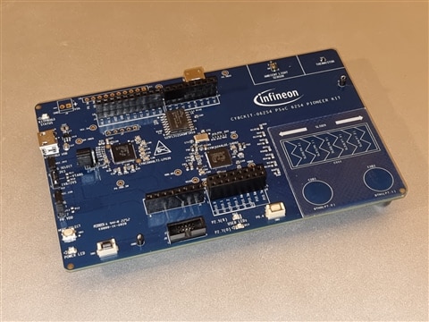
The idea for this project came to me while looking at this PSoC62 Pioneer Kit. On the PCB it features a "Touchpad" which reminded me of a Joypad. The challenge launched by Element14 together with Infineon proposed reaching the limits of this system, trying to exploit the characteristics of the on-board microcontroller.
As I explained in my posts during this challenge, I'm a retro enthusiast and have written several emulators in the past. My favorite system, which was the first one I had in my youth, is the SEGA SG-1000 console. So I wanted to rewrite one of the SEGA SG-1000 emulators that I have written and port it to the board in question.
1.1 - Difficulties and limits

Emulating a game console is a rather complex, resource-intensive project. I thought it was a perfect candidate to push the PSoC62 Pioneer Kit to the limit.
I can say that an emulator is divided into two main areas: Virtual Machine and Hardware Input/output. The microcontroller on board is a dual-core Arm Cortex M4/M0+, so I can divide these areas into one core each.
The two cores are configurable through the ModusToolbox ecosystem, so it is possible to decide how to divide the resources between the two cores, and at what speed to set the clocks. For me, it was a nice surprise to see the high customization and ease of use of ModusToolbox.
In the end, I decided to set the CM4 core at 150MHz and the CM0+ at 75MHz. I left the emulation of the Input/Output hardware components at the CM0+ core, and the execution of the virtual machine at the CM4 core. That means that the cm0+ will generate the VGA video and the audio signals, it will handle also the Capsense joypad, and it will synchronize the execution of the virtual machine in the CM4 core.
Another aspect that is difficult to manage is the division of the SRAM between the two cores. The original hardware to be emulated has 2Kb of RAM, 16Kb of special VRAM used by the Video Display Processor, and last but not least, the memory used by the game cartridge.
The Infineon PSoC 6 MCU in the Pioneer Kit is the CY8C6244LQI-S4D92, which has 128Kb SRAM and 256Kb flash ROM. Apparently, everything should work perfectly, but it is not so obvious. The microcontroller must generate a video signal, which for the console to be emulated, must have a resolution of 256x192 pixels, therefore, unless it were possible to generate all the graphics on the fly, a frame buffer of about 49Kb is needed to host a video frame.
Then, in the same way, the audio generation relies on a buffer that contains all the samples to stream. in this case, we need one of around 1Kb (more on this later). Don't forget that the source code of the emulator will create variables, temporary buffers, etc. in a stack, so you need to give a reasonable space to stack and heap.
Speed is also crucial, since the cm0+ core must be able to generate a standard VGA signal, and the CM4 core must be able to perform a number of calculations to emulate a 3.58MHz CPU, a 10.74MHz VDP, and a Programmable Sound Generator (PSG) at 3.58MHz, in order to display graphics, sound and manage a Joypad in real-time.
Two months were available for this project, so I had to accept a compromise between the quality and usability of the emulator.
1.2 - The emulator and the game
Two months were available for this project, so I had to accept a compromise between the quality and usability of the emulator.
The emulator will have to perform different tasks divided into time intervals so that it is possible to simulate hardware composed of several units that work in multitasking. Since the emulator is synchronized with a video signal, the time intervals will be equal to a video scanline. Then, the Z80 virtual CPU will run for a series of cycles equal to the time interval of an emulated video scanline, and then the graphics and sound for that scanline will be rendered.
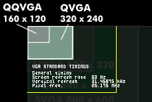
I won't go too much into the details of the emulation, but this means that considering the VGA standard timings:
Horizontal timing (line)
Polarity of horizontal sync pulse is negative.
| Scanline part | Pixels | Time [µs] |
|---|---|---|
| Visible area | 640 | 25.422045680238 |
| Front porch | 16 | 0.63555114200596 |
| Sync pulse | 96 | 3.8133068520357 |
| Back porch | 48 | 1.9066534260179 |
| Whole line | 800 | 31.777557100298 |
Vertical timing (frame)
Polarity of vertical sync pulse is negative.
| Frame part | Lines | Time [ms] |
|---|---|---|
| Visible area | 480 | 15.253227408143 |
| Front porch | 10 | 0.31777557100298 |
| Sync pulse | 2 | 0.063555114200596 |
| Back porch | 33 | 1.0486593843098 |
| Whole frame | 525 | 16.683217477656 |
I need to render a complete scanline (CPU + VDP + PSG + IO) in 31.777 us. It may seem like an impossible mission, but there are tricks that we can use to do it. So this should be the final result of the game that I want to run on this emulator:
https://youtube.com/watch?v=Of_kFSOZSxo
And this is the same game emulated by the PSoC62S4 Pioneer kit:
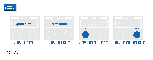
I decided to use "Space Invaders" for one reason only: The Capsense area present on the Pioneer Kit has 1 axis direction slider and two buttons, which is perfect for this game. I used the slider as a rotary encoder, and the two buttons as normal fire buttons.
Let's examine the architecture of this project in the following schematic:
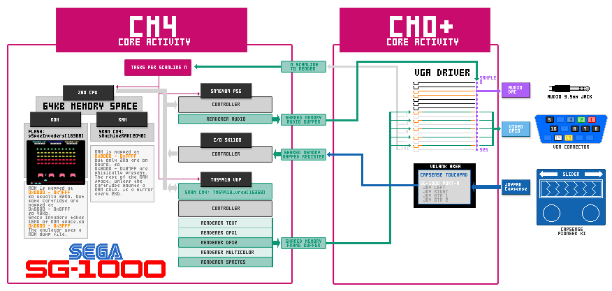
This schematic shows clearly that the hardware interface of the emulator is handled by the CM0+ core, while the software emulation of the console is left to the CM4 core. In ModusToolbox the system is configured for using the external 24MHz clock on the Pioneer Kit that offers a better accuracy and stability of the operating frequencies for the cores.
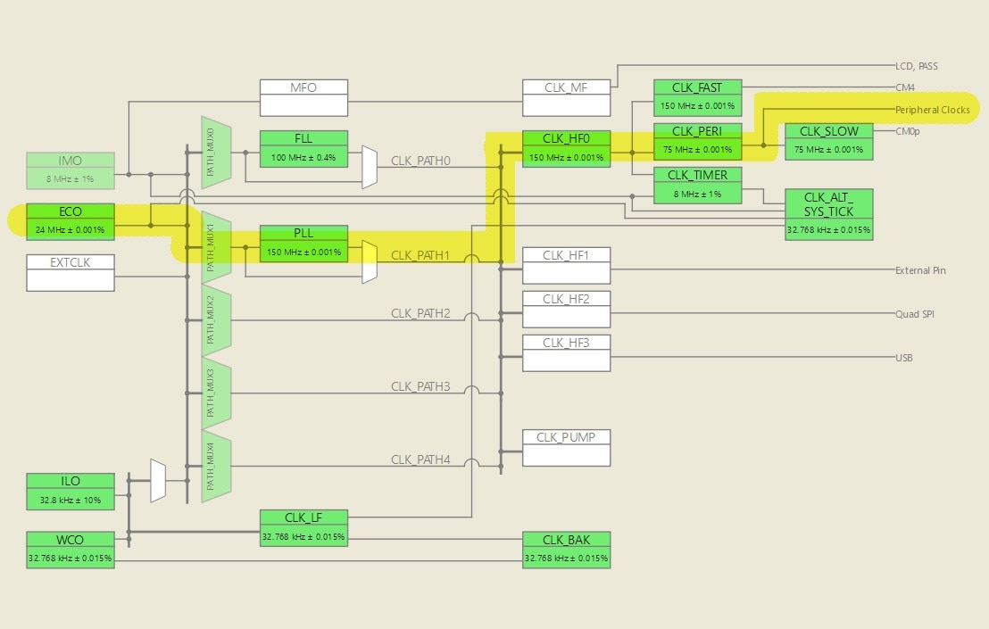
The routing shown in the system schematic of the ModusToolbox Device Configurator sets the clock for the CM0+ core to 75MHz, and the clock of the CM4 to 150MHz. So the minimum time interval of the Peripheral Clock is 13.33 ns, enough for the timers and the DMA functionality.
2.1 - Hardware side on CM0+
The CM0+ core takes care of driving the hardware interfaces for the emulator, such as Video, Audio, and I/O. So I started first with the development of the VGA video driver since it's the unit that rules all the emulation.
2.1.1 - VGA DAC
As I mentioned earlier, the video signal generated complies with the VGA standard, therefore with a vertical frequency of 60Hz and a horizontal one of 31.468 kHz. The vertical resolution maintains the standard of 525 total lines for a visible vertical area of 480 lines, while for the horizontal resolution, we will use a "Pixel Clock" which we will configure to obtain a resolution suitable for the emulation.
The Pioneer Kit does not have a VGA video output, but building it is very simple and requires a few resistors, a DE15 socket connector, some jumper wires, and a solderless breadboard. All components can be easily found on eBay or Amazon, but I wanted to bring your attention to this solderless VGA socket:
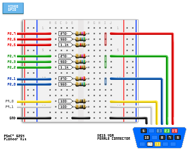
This little circuit is a triple analog-to-digital converter that takes the values of Red, Green, and Blue and converts them into voltages using simple resistors. The proposed circuit offers a resolution of 8 shades of Red and Green, while only 4 for Blue, which however are sufficient for the visual impact. This division is called "color depth" and is usually referred to as "BPP" or bits per plane.
The signal will therefore be rgb332 and will allow us to obtain 256 colors and the following palette.
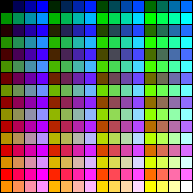
This color depth is very useful because it fits right into a byte, making it easy to match 1 pixel to 1 byte. Here we understand why to match an entire GPIO port to the used RGB signals.
2.1.2 - Audio Signal
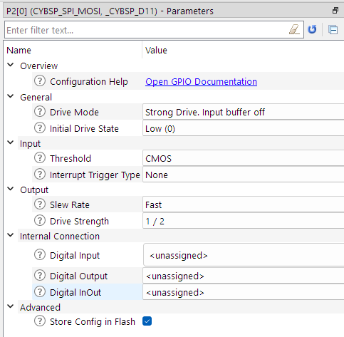
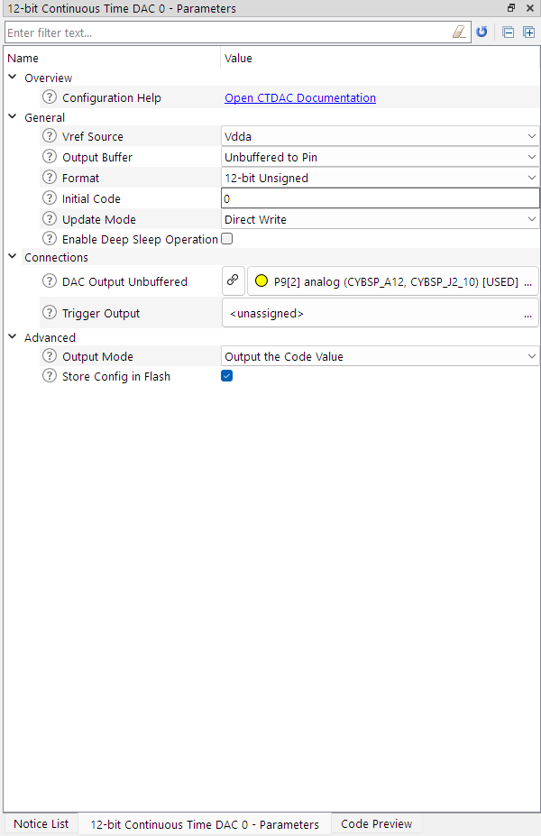
The audio signal is generated by the DAC embedded into the PSoC62, and it is fed by the virtual PSG of the emulator. The simplest hardware you need to plug your Pioneer Kit is a bipolar shielded wire for audio signals and a 3.5mm stereo jack plug.
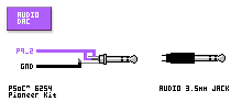
The resolution of this DAC is 12 bits, this means that the signal coming out of the assigned GPIO can assume 2^12 values to modulate a voltage between 0 and 3.3v (typically).
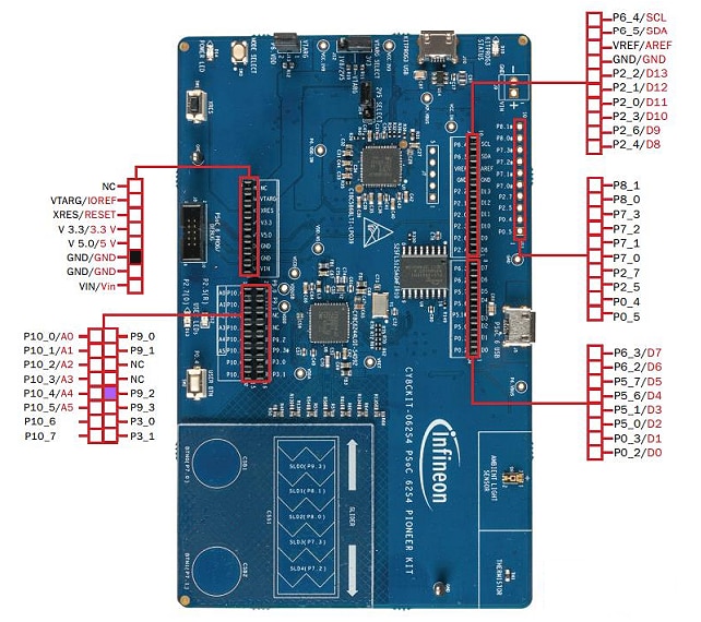
2.1.3 - Capsense Joypad
The Pioneer Kit has some capacitive areas on board that are connected to specific pins of the PSoC62. These pins can be dri0ven with the Capsense technology which simplifies the configuration and the building of capacitive devices. In this specific project, this interface reminds us of a one-axis joypad with two fire buttons. So, it's possible to use it directly as an input device by configuring it through the Capsense configurator.
2.2 - Software side on CM0+
The project was derived from the "Dual-CPU Empty PSoC6 App" example project within ModusToolbox. As shown above, I modified the clock system, and the Board Support Package, and from there I added various video, audio, and joypad devices.
2.2.1 - VGA Driver
The VGA driver is capable of generating a video signal that complies with the VGA standard, so it should be compatible with most TV/Monitors that can connect to a PC.
The generated signal consists of the generation of 60 frames per second composed of a sequence of 525 scanlines. The scanlines are divided into groups or areas: Vertical Sync, the Back Porch which precedes the actual image, the Active Area with the image made up of 480 lines of pixels, and finally the Front Porch which closes the image.

For more details, you can check my posts on this blog, but here I can say that all the scanlines are composed of the two sync signals (Horizontal and Vertical), ad the three color signals (R, G, B). In all scanlines, there is a horizontal sync pulse, and the vertical sync signal is high, except for the vertical sync period, which presents two lines with a low state for the vertical sync.
The color signals are at a blank level (black) in all scanlines except in the Active Area, where they are modulated thanks to the data coming from the frame buffer and combined together by the resistor DAC.
To send the correct line, the driver counts the scanlines within an interrupt service routine (ISR), which is triggered at the end of each line via an IRQ event. In order to execute a line with the correct characteristics, a Counter with a PWM signal is used, which integrates an impulse, in this case negative, corresponding to the horizontal synchronism of the standard VGA signal. In addition, two "Counter Compare" events are set along the line to activate the RGB signals and therefore the streaming of the pixels at regular intervals, according to a "Pixel Counter".
We have seen that the graphics resolution of the SEGA SG-1000 is 256x192, and the resolution for the VGA signal is 640x480. We can double the original resolution and get a bigger picture. For horizontal resolution, we just need to "slow down" the PIXEL Clock, while for vertical resolution we can transmit the same line twice.
We have seen that the graphics resolution of the SEGA SG-1000 is 256x192, and the resolution for the VGA signal is 640x480. We can double the original resolution and get a bigger picture. For horizontal resolution, we just need to "slow down" the PIXEL Clock, while for vertical resolution we can transmit the same line twice. Since we are emulating a console that typically used to be hooked up to a CRT television, we can transmit one line, and turn off the next line to create the typical effect of scanlines. We also need this trick to free up access to the frame buffer in RAM while the CM4 core accesses it during the rendering phase.
Let's examine how this system works:

I extracted a sample of Active Area scanlines. As I explained before we have a scanline containing the pixels of the graphics, and subsequently an empty scanline (black) where no pixels are transmitted but the CM4 core has free access to the SRAM for rendering the graphics.
That said, let's analyze the active scanline, here's what happens.
The signal begins with the negative horizontal sync pulse, lasting 3.81us. For this purpose, I used a TCPWM counter which I set with the "Device Manager".
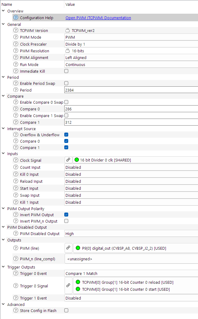
Calculating the appropriate values is simple because the timer counts the time at each clock cycle, which for peripherals is 75Mhz. So each cycle lasts 13.33ns, and so to get the 3.81us pulse, I have to set the Counter Compare 0 to 3810ns /13.33ns = 285.82 cycles, so 286. Along the scanline, this is the HSync area.
After that, there is the Back Porch that ends at the "Counter Compare 1", and at this point, the streaming of the pixels starts. So at the compare 1 match, a second TCPWM is started. This one is the Pixel Clock, which runs continuously until all pixels of the scanline are transmitted.
Here the Pixel Counter counts 7 cycles, and then it triggers a DMA transfer, which copies one byte from the frame buffer to the GPIO port connected to the RGB DAC. Here 7 cycles (0..6) correspond to 93.31ns, which visually corresponds to the width of one pixel. Every DMA transfer decrements the number of pixels to stream. This number is set in the DMA configuration.
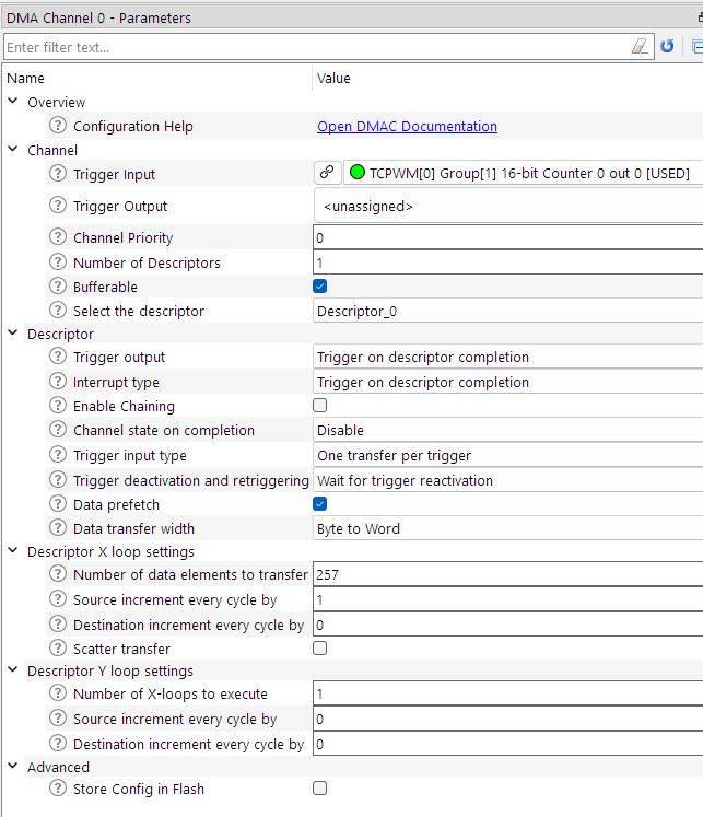
As soon as the "Number of data elements to transfer" reaches 0 the Pixel Counter is stopped. Why 257 since the horizontal resolution is 256? When the GPIO port receives one byte from the DMA, sets the pins 0..7 to the state of all bits of the byte.
The pins of the port remain in their state until a new transfer from the DMA. That's why a pixel is 7 cycles wide, and that's why pixel 257 is used to stop the RGB signal because it's always set to black. When the first TCPWM reaches the end at cycle 2384 (2384 * 13.33ns = 31.778us) the scanline ends, the IRQ event fires, and the ISR is called.
Within the ISR the scanlines are counted, and as we saw in the schematic, the frame is composed.
After a scanline is shown the DMA is disabled, so the Pixel Counter won't trigger a memory transfer and the SRAM is free for any operation by the CM4. So the ISR sends a message to the CM4 core containing the number of the next scanline to render, so for the next scanline pixels data are ready to be streamed to GPIOs.
2.2.2 - Audio Driver
Generating a digital audio signal is pretty simple and has several ways to do it. We are fortunate that the PSoC6 has a Digital Analog Converter (DAC) which can be configured to continuously convert a digital value into an analog voltage level in real-time. To obtain a sound we just need to vary this level over time, in order to create oscillations. This signal applied to an amplifier and a speaker, is output as a sound.
To generate a sound with the DAC we need a buffer that contains a series of data to be sent in sequence, and a counter/timer to send the data at regular intervals to the DAC. The rate at which data is sent determines the sample rate of the sound. To reproduce previously recorded sounds, we must necessarily use the same sampling rate, but since the sound is generated by the same application, i.e. the emulator, we have the freedom to decide the frequency ourselves.
Since we need to synchronize audio to video, we can take advantage of the video driver to send an audio sample to each scanline of the screen to get as close as possible to a faithful reproduction of the audio generated by the PSG.
I won't go into detail about the SN76489 PSG emulation, what is important to know is that the code renders an audio sample for each scanline in sequence at each call. Thanks to ModusToolbox, the basic configuration of the DAC is very easy since we need only to send data to it.
for sending the audio samples to the DAC, we just have to use the appropriate function at the beginning of each scanline within the ISR of the VGA driver.
//
  Cy_CTDAC_SetValue(audio_dac_HW, gAudioBufferFront[gVGAScanline]);
//
As already mentioned, the audio samples are read from a buffer, which frame by frame is exchanged with a secondary buffer on which the emulator has prepared new samples to be sent to the DAC. This technique is called double buffering.
//
  tmpPtr = gAudioBufferFront;
  gAudioBufferFront = gAudioBufferBack;
  gAudioBufferBack = tmpPtr;
//
2.2.3 - Capsense Joypad Driver
The Capsense system of the Pioneer lets you configure and tune the capacitive areas on board.
For this project, I wanted to use the example provided by ModusToolbox as a starting point. This makes it more familiar to everyone. The example configures the horizontal slider as a linear potentiometer, while the two buttons as simple push-buttons. To turn it into a capacitive joypad, I changed the main function to read the slider as if it were a rotary encoder.
This means that variations of increasing values on the slider correspond to a movement to the right, while variations of decreasing values correspond to movements to the left. Having said that it's just a matter of coordinating the call to this refresh function at the time the screen is not being refreshed, ie during the vertical blank area.
What I think is important is to configure the controls well in the Capsense Tuner.
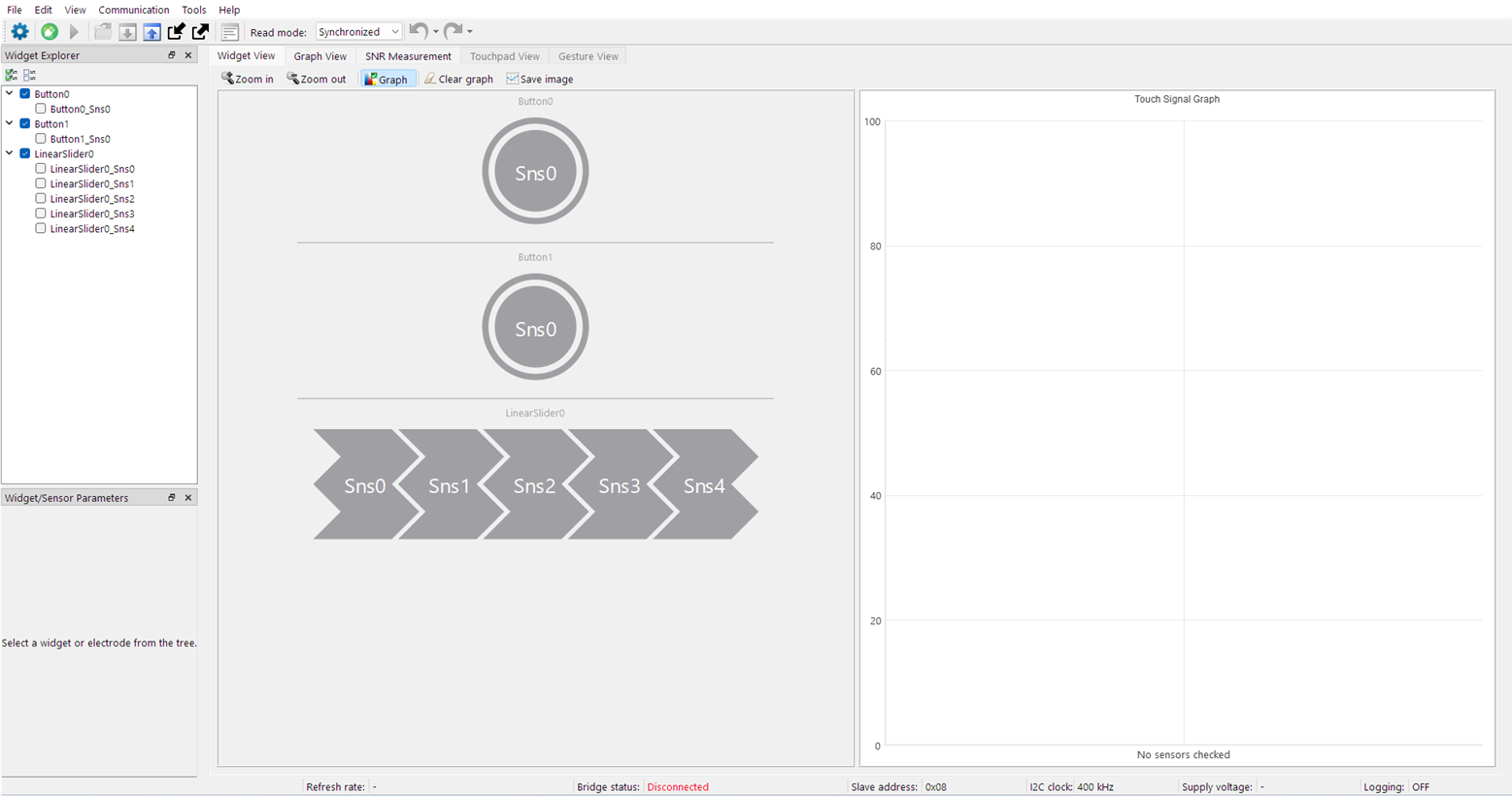
To obtain "clean" and smooth movements it is necessary to instruct the tuner by providing him with a profile on the background electromagnetic noise and on the signal level when the areas are touched with the fingers.
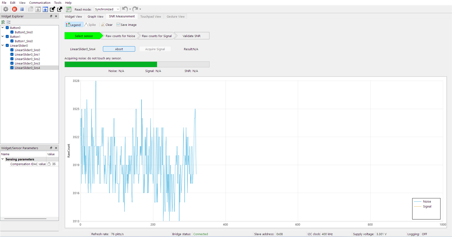
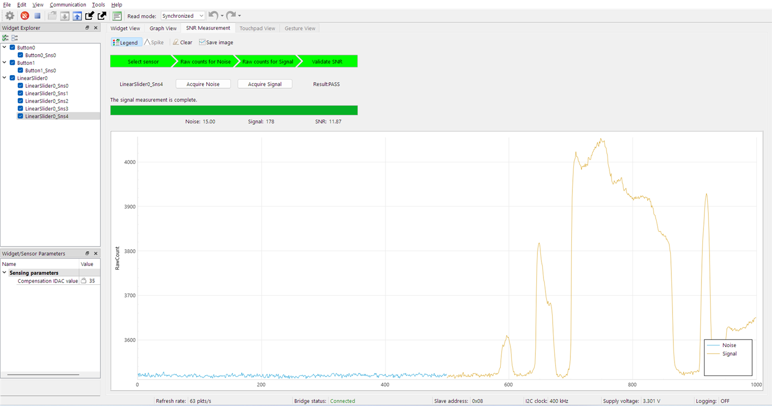
Once the profile has been created for all the capacitive areas, it is possible to test the controls, either through graphs or by viewing the levels. I am amazed by the Capsense system because it's unbelievable the amount of time and work that saves you.


I'll leave the details in the source code for further reading.
2.3 - Software side on CM4
Since the CM4 core is faster, it takes care of running the entire emulator but lets the CM0+ core handle the synchronization. Explaining and detailing the hardware of the SEGA SG-1000 console would be long and cumbersome in this context, so if it is a topic of interest, I will continue the project later. The important point is how I made the two cores communicate.
In section 2.0 - Architecture, I showed that both cores have read and write access to specific memory locations. These locations function as memory-mapped registers. As I explained in this blog, I preferred to use this system because I found it to be faster than the IPC.
Since the CM0+ core needs to request the next scanline to be rendered quickly while a black line is displayed, reaction times are crucial.
2.3.1 - Memory mapped registers
This system is very simple and relies on the use of SRAM which is shared by the cores. In practice, one core writes a value to one of these registers while the other core waits for that given register to assume a non-zero value. The calling core, after having written the value, eventually waits for it to return to zero, a sign that the second core has read it and therefore reset it.
This method is simple but care must be taken to handle pointers well. Better to create a common file for both cores, with the definition of an address map in the SRAM.
// Within the source file *.c
volatile uint32_t gCommandAddr      = (SHARED_MEMORY);
volatile uint32_t gCmdAddr          = (SHARED_MEMORY + 4);
volatile uint32_t gVBlankAddr       = (SHARED_MEMORY + 8);
volatile uint32_t gVideoBufferAddr  = (SHARED_MEMORY + 12);
volatile uint32_t gAudioBufferAddr  = (SHARED_MEMORY + 16);
volatile uint32_t gIOAddr           = (SHARED_MEMORY + 20);

// Within the header file *.h
extern volatile uint32_t gCommandAddr;
extern volatile uint32_t gCmdAddr;
extern volatile uint32_t gVBlankAddr;
extern volatile uint32_t gVideoBufferAddr;
extern volatile uint32_t gAudioBufferAddr;
extern volatile uint32_t gIOAddr;

// Macros
#define _SHARED_gCommand  *((uint8_t*)(*((uint32_t*)gCmdAddr)))
Later, where necessary, it will be easy to write to the registers and create a waiting cycle for them. In the following example, the core CM4 is waiting to receive a value from the core CM0+.
// cm0+
for (;;)
{
  _SHARED_gCommand = 1;
  while (_SHARED_gCommand) {};
}

// cm4
for (;;)
{
  while (_SHARED_gCommand == 0) {};
  _SHARED_gCommand = 0;
}
2.3.2 - Emulator Architecture
A software computer emulator has to emulate all the components in a real computer using software programs over another computer or hardware. Basically, it's based on a virtual machine (VM) like Java and others. A virtual machine is any kind of computer that does not exist as real hardware but it is implemented by software. All hardware components that are in the hardware to emulate, actually are translated into code that will mimic as accurately as possible the behavior of the component.
In section 2.0 - Architecture, is shown the main schematic of the SEGA SG-1000 hardware. In my emulator, the various active components perform certain functions that can be called cyclically such as rendering graphics or video. In theory, to simulate hardware in real-time, all the components should execute a piece of program each in sequence, thus exploiting a memory-mapped register, at each scanline the CM0+ core calls the code parts in the CM4 core which executes program parts of the game.
Now, the problem that arises is respecting the times of the Video Driver, in fact, a video scanline lasts 31.778us, therefore the emulation corresponding to the time that the console takes to calculate everything necessary to draw a scanline, must last that time. This is very difficult, and a 150MHz CM4 core frequency is a bit low to do everything.
What I thought of doing is dividing the tasks into two different moments.
I will try to explain as best as possible and briefly how the SG-1000 works.
As soon as you turn on the console, the Z80 CPU starts reading the code from the ROM contained in the cartridge. Running game code will ask the Z80 to read and write data to RAM, prepare graphics by accessing VDP registers, or change frequency to PSG audio oscillators.
The VDP and PSG also have continuous output which is affected by internal registers which are modified by the Z80. Usually to obtain some stability the Z80 accesses these components when the VDP is not drawing the video frame. Then, to reduce the number of operations that the CM4 core has to perform in the time of a scanline, I can render only the graphics during the Active Area of the VGA signal, and subsequently during the vertical blank area, run the Z80 and render the samples audio.
Summing up, this project allowed me to get to know the PSoC62, and at the same time share a learning path with all of you, developing an application that could push this MCU to the maximum.
An emulator requires a lot of resources, and so I set myself this challenge, but what are the limitations I've encountered?
First the 128Kb memory for a project that uses graphics and sound is limited, especially if you need a video frame buffer to render to. Suffice it to say that if we want to implement an RGB video driver we have to spend 76800 bytes for a frame buffer with a resolution of 320x240. This emulator has been heavily modified to run "comfortably" with this amount of SRAM.
However this emulator could support all titles released for SEGA SG-1000, but obviously, in the short time available it was tested only for the proposed game "Space Invaders". On the other hand, a heavy limitation for the choice of the game is given by the presence of only one axis for the capacitive joypad.
As far as speed is concerned, you have to pay close attention to how to configure the clocks, bearing in mind that both cores share the same clock source and the frequency of the two cores must be balanced with dividers, therefore the maximum obtainable is 150Mhz on CM4 and 75MHz on CM0+. If, on the other hand, you want to reach 100MHz on CM0+, the CM4 core also drops to 100MHz.
Another aspect to consider is the use of memory which is shared, and for correct use and based on the application to be developed, it may require the configuration of the protection units, as well as the synchronization of accesses by the two cores.
Otherwise, the tools offered by ModusToolbox are extremely useful and easy to use. I am very happy with this experience, and I hope I have left something for everyone by turning the Pioneer Kit into a mini-game console.
3.1 - The project
This project has been documented during the "At the core" design challenge at the Element14 community, you can read all the posts of the blog here:
At the core design challenge winner blog: SEGA SG-1000 Emulator on PSoC62
