Example program using an ESP8266-12E to power a 4 switch 5V relay with web server, and wifi client/AP mode including email alerts with SMTP/Postmark
##PARTS:
OPEN-SMART ESP8266 ESP-12E Development Board Serial Wi-Fi Module
4-Channel 5V 12V Relay Module w/ Optocoupler ###Note: requires OPTOCOUPLER to power relays from 5V VIN, while powering the input lines from the 3.2V lines from the esp8266
#IMPORTANT NOTES
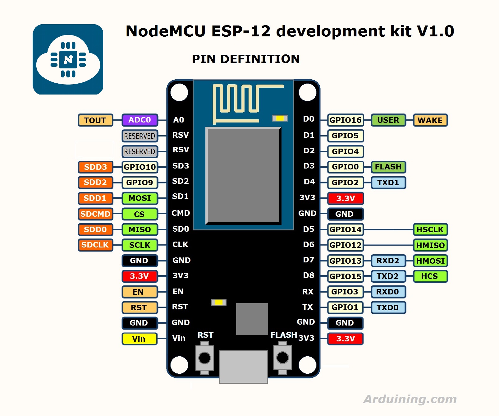
IMAGE File to esp8266 pinouts [ ESP8266-12E Pins ] (http://crufti.com/content/images/2015/11/nodemcudevkit_v1-0_io.jpg)
-
Some 5V boards will automatically "toggle" and relay when the board is first powered on. This causes a problem with an NO line which should never be closed unless intentionally done (like for a garage door) to handle this I power the 3.2V to the relay board from pin 12 and not the 3V out on the ESP8266. this revents that initial toggle on a power on.
-
Using an OPTOCOUPLED Board is a required, this isolates the 5V from the 3.2 pins in the ESP-8266
-
There is a 301 redirect to / on the webserver, and some browsers (mobile) will do an unintentional "refresh" in the browser if you switch activies then come back later.. the redirect to / prevents this from toggling a swith when not intended.
-
I found postmark a better way to send email then with Auth'd SMTP. it's quicker and easier to debug / log.
-
in case the ESP8266 cannot connect to an AP as a client, it will go into AP mode, and you can connect directly with the PSK in code.
-
I have alternate userid/pass words just in case multiple people use it.
-
there is an optional "garage mode" which just exposes/uses the bounce (short close then open) mode to support garage door switches.
Have Fun.
