Comments (34)
 Octogonapus
commented on August 18, 2024
Octogonapus
commented on August 18, 2024
If you're trying to slice a CSG into a planar polygon, how are you going to account for the inherent loss of geometry detail when projecting a 3D object onto a 2D plane? Simply taking a thin slice and performing a projection transformation on that isn't going to carry over detail in the thickness of that slice. If the slice was infinitesimally thick, then you'd end up with an infinite number of slices, but no loss in detail (and for obvious reasons, this isn't a practical solution).
from jcsg.
 madhephaestus
commented on August 18, 2024
madhephaestus
commented on August 18, 2024
Here is my first thoughts, this won't be the most efficient, but will be a good starting place. Take your part and transform it by the inverse of the cut plane (this should be changed to Transform from Plane maybe?). Then make a intersection of a cube whose dimensions are the x and y min/max values and the thickness in the layer height. Then you can go through the polygons of the remaining shape and prune out any polygons that have a point where z is not 0. This will give you back the polygons of exactly the shape at the cut plane.
from jcsg.
madhephaestus
commented on August 18, 2024
As for the detail loss, this is inherent in machining and manufacturing of all kinds, what you make is never actually what the computer defines. The computer can compute shapes to any arbitrary precision. The slicer, based on the 3d printer or milling settings, will step through the piece at whatever compromise between precision and machining time the user prefers. Bis trade off will be done at the layer above this function, and should not effect the data that this code is given or generates.
from jcsg.
madhephaestus
commented on August 18, 2024
Hopefully after years of experience with these things @sjkelly might have some insight on this as well.
from jcsg.
Octogonapus
commented on August 18, 2024
As you can see in my latest commit, I changed the ISlice interface to take a slice plane input as a double. Is a Transform really necessary? If you just want to specify the z coordinate of the slice plane, this seems to do the job just fine. However, if you want to slice on some weird axis, I can see a Transform being necessary.
from jcsg.
madhephaestus
commented on August 18, 2024
I'm ok with that, but i can imagine a few cases where I would use this to slice some weird plane, like the plane where the servo connects to the body?
https://github.com/madhephaestus/BancroftMakerspaceProject2016/blob/master/bodyGenerator.groovy#L111 is how to move a CSG using just the transform object
from jcsg.
Octogonapus
commented on August 18, 2024
For reference, I added the Transform method. I'm scaling it by the inverse of the current scale so that the scale doesn't mess up the matrix inversion. Is this the right thing to do, or can I ignore scale in the matrix inversion?
from jcsg.
Octogonapus
commented on August 18, 2024
It just seemed unnecessary; however, if you think a general Transform would be useful, I can keep the latest commit.
from jcsg.
madhephaestus
commented on August 18, 2024
Instead of making a giant cube (which may not be giant enough), why not use the introspection of its own size: http://neuronrobotics.com/JavaCAD/Measurment/ that way the cube if set to the bounds of object it will always be exactly the right size.
from jcsg.
Octogonapus
commented on August 18, 2024
I figured having a final CSG would be faster. Feature added. I've left the z-height at 1 (afaik, the height doesn't matter, so why not stay in the Integer realm?)
from jcsg.
madhephaestus
commented on August 18, 2024
Since the values of z are floating point numbers you can not check ==0. You should do a bound check (or make a bound check function) to check if a value is +- some value simply int casting at this point can cause some surprising results, so always do the bound check.
also when doing long stream calls, flatten them to new lines each time you do a method call. Or let the IDE auto-format the section.
from jcsg.
Octogonapus
commented on August 18, 2024
I think that I can check at == 0 because I'm the CSG used as the slice plane has a face at z == 0, is this still not correct? I tested this algorithm the other day and it worked for my test object. If I use two bounds instead, then what would those be?
from jcsg.
madhephaestus
commented on August 18, 2024
+- 0.001 mm is good, it just catches datatype clipping. Just because you computed something that should be a float at 0 doesn't mean it is...
from jcsg.
madhephaestus
commented on August 18, 2024
You should add unit tests for a shape with a hole in it. You should include some convex shapes as well (like the letter C). How might you verify that the shapes that your algorithm gives back are "correct"? Can you make a test that checks the points and fails if they are wrong?
A cube with a smaller cube cut from its center would make a good cross section, and would be easy to calculate what those 8 points should be.
Maybe making an export to DXF and loading in the DXF might be a good way to test?
from jcsg.
Octogonapus
commented on August 18, 2024
Is there an easy way I can view the CSG's I'm getting from these tests? I tried outputting to an OBJ or an STL string, putting that into a Gist, and then loading that Gist with Bowler Studio, but both formats have errors.
from jcsg.
Octogonapus
commented on August 18, 2024
I put the OBJ into Blender, and it's being imported correctly. Perhaps this is a Bowler Studio error?
from jcsg.
madhephaestus
commented on August 18, 2024
the STL should have worked, except its a binary file format, so you have to use the code to write the file. You can also open stls in Cura to quickly look a them.
InkScape is a good way to look at DXFs
Once you get a look at whats coming out, you should start with unit tests of what the correct data should be. This is called Test Driven Development. You then adjust your algorithm to pass the tests. It means you are always building testing into your code as you go which is a good habit to have.
from jcsg.
Octogonapus
commented on August 18, 2024
I'm not getting any faces, though. I'm getting all the points needed to describe the slice (plus some extra in one test, but this is out of my control), but no faces are being generated. I think this is also out of my control, as .toObjString method is in CSG. As far as the slicer is concerned, it just needs to output a list of points, which works just fine.
from jcsg.
madhephaestus
commented on August 18, 2024
Hmm, we need to change the return type to
List< List<Vector3d>>
not
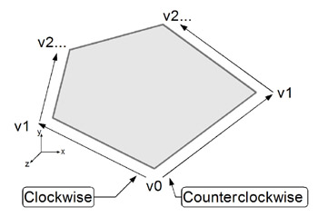
List<Vector3d> , since any time there is more than one shape (a hole), more than one polygon should be return representing the polygon of each outline. Note that outside shapes need to be wound (the order the points are in) counterclockwise, and inside shapes need to be wound clockwise. The winding is a way of analytically determining if a polygon is an inside or outside feature. Knowing inside or outside will also be necessary when doing the insets (positive insets are towards the outsides). Think right-hand rule for the polygon and your palm faces the inside of the original shape. For inside shapes, the as your fingers go from start of polygon to finish your palm should also face the inside of the original shape.
note there are helper functions to detect winding order:
https://github.com/Octogonapus/JCSG/blob/master/src/main/java/eu/mihosoft/vrl/v3d/Extrude.java#L184
from jcsg.
madhephaestus
commented on August 18, 2024
this is looking good!
from jcsg.
madhephaestus
commented on August 18, 2024
I like the list of polygons as a return better, since the test for winding order is that data type.
from jcsg.
Octogonapus
commented on August 18, 2024
Can you explain to me this inside/outside feature business? It's not making much sense to me since we're talking about a 2-D plane.
from jcsg.
madhephaestus
commented on August 18, 2024
Polygons are defined by having a encapsulated space that is "inside" the polygon. To denote that this, a polygon defines the outer boundary using counterclockwise winding order. Now, some polygons are meant to represent "holes" in other polygons. "Holes" are polygons with clockwise winding order. This also means that any "Hole" bust be entirely inside a non-"hole" polygon.
A place this is used is when defining tool paths, and most importantly when doing insets, this definition is critical. A CNC tool must ride outside of the part, not along its "line" because the tool has some thickness to it, and it needs to know what part is the outside, so it knows where the tool can go. For insets, the inside is the direction that the surface of all the lines move (in or out). In fact, the best way to calculate the inset is to simulate a circle moving tangent to the line (step by step in tiny increments, those increments being something like the minimum step size for your printer), and calculate its center as it moves tangent to the lines, then switching to a new line when the circle intersects another line.
Like this object: https://gist.github.com/07f489d46d23ceac8a1e8b3779719e9b
from jcsg.
madhephaestus
commented on August 18, 2024
here is a nice graphic: http://flylib.com/books/2/124/1/html/2/files/figure12-6.jpeg
from jcsg.
Octogonapus
commented on August 18, 2024
So any polygon which has a hole needs to be wound clockwise? I have a way to detect holes Euler's polyhedron formula, but I need to get an edge count for it to work. Know of any good way to get edges?
from jcsg.
madhephaestus
commented on August 18, 2024
so in this object: https://gist.github.com/07f489d46d23ceac8a1e8b3779719e9b
Will produce 2 polygons. The large polygon (40 mm on a side) will be counter-clockwise, and the smaller one, (20mm on a side) will be clockwise.
from jcsg.
madhephaestus
commented on August 18, 2024
Hows it going?
from jcsg.
Octogonapus
commented on August 18, 2024
I haven't made much progress on the whole winding thing. I picked up a job since I last worked on this and have been busy since. I really don't know how to detect winding-dependent features out of an array of vertices. If I did, then this wouldn't be a difficult implementation.
from jcsg.
madhephaestus
commented on August 18, 2024
I'm not sure there is anything wrong in the implementation, it just needs a bunch of unit tests to verify that what it's giving back is what you expect it would. It may be generating triangular decomposition of the shapes, which might be whats throwing you off. After you have the list of all polygons that are at z0, you then go through them to create the actual polygons you intend to return. You will use the brushfire search to search through the points and form the outer polygon first. Start at a point outside the polygon and calculate an ever increasing circle until the first point in your list is inside the circle. thats a point that is on the outside of the final shape. Start there and do the same increasing circle trick to find the next point on the outer surface. To figure out if its the next point, you check to see if a point just to the right of the line is outside, and just to the left is inside (be careful for edge cases, like straight, folded over and 90 degree angles) . In this process you make a new list for this polygon. The polygon is done when you get back to the starting point. If there are points left in the original list (assuming you pop out the points as you add them to the outer polygon), you repeat the process until all points are pulled out of the original list. Once you are done, and all the polygons are now the outer surfaces rather than the triangle decomposition, you check each polygon to see if all of its points are inside any other of the polygons, and if so, use the existing API to reverse the winding order for that polygon.
To test if a point is inside a polygon, and there a bunch of tricks for that: http://www.blackpawn.com/texts/pointinpoly/
Heres another track you could explore. Convert the layer to an image (using some JavaFX API's) from the layer you are looking at. Maybe color it black and contrast it with a white background then make a png of the image of the cross section. Then hand that to OpenCV to process into the list of polygons (it has a function that takes images poops out the polygon data we want) This would need to be done in bowler-scripting-kernel or in BowlerStudio as a script since JCSG doesn't have Opencv (and its not trivial to just add in a way that deploys nicely)
from jcsg.
madhephaestus
commented on August 18, 2024
I found this library that may be very helpful in converting the flat versions into paths.
https://github.com/madhephaestus/imagetracerjava
I took a quick stab at using it: https://github.com/NeuronRobotics/BowlerStudio/blob/development/src/main/java/com/neuronrobotics/bowlerstudio/threed/SVGFactory.java but it needs lots of fine tuning to generate a sane input png.
from jcsg.
madhephaestus
commented on August 18, 2024
https://github.com/madhephaestus/imagetracerjava works however it is a very slow and not very precise (converting to image then generating vector from images) I'm losing at least +-.5mm just in the conversion and it takes many seconds to complete. BUT, if you read the algorithm this code is using and search through your vector lists instead of searching through the pixel image like he is, then your version could be SUPER fast and exact.
from jcsg.
madhephaestus
commented on August 18, 2024
@pseudoeuclidean THis issue might be a good place to start with a slicer function.
from jcsg.
madhephaestus
commented on August 18, 2024
@pseudoeuclidean I took a close look at the coincident edge detection and found an issue. There are situations where one edge will be totaly overlapping with a second edge, but that second edge is longer than the first one. If the long edge is erased then the there is a mesh gap. If the the small one is erased, then the long edge cuts through the polygon forming an invalid shape. What will need to happen is when an edge is partially overlapping, then the long edges need to be broken into short edge sections and the triangulation needs to be re-run to deal with the new edge structure. I think this is why the edge pruning is failing.
from jcsg.
madhephaestus
commented on August 18, 2024
This is resolved in https://github.com/NeuronRobotics/JCSG/blob/development/src/main/java/eu/mihosoft/vrl/v3d/Slice.java
from jcsg.
Related Issues (20)
- Text3d support HOT 4
- Quantizing vertices? HOT 11
- License HOT 2
- How to make a csg from complicated svg? HOT 6
- WeightedTubeSample example causes StackOverflowError HOT 1
- STL file generated for a simple Polyhedron (L shape) : one face should not be part of the model HOT 3
- CSG class : issue in OBJ file generation : faces are not saved HOT 2
- Calculate Volume of CSG
- parallelstream must not do an addAll to an ArrayList: it causes null entries HOT 1
- Stackoverflow HOT 4
- Union and Difference Coplanar Polygons HOT 4
- How to import OBJ ? HOT 5
- Creating a Polygon HOT 5
- Split in two objects after difference HOT 1
- Multiple uinions cause StackOverflow Error HOT 2
- How to set color to Java JCSG object? [JavaFX] HOT 2
- Bounds intersection not implemented
- Cylinder rotation in Z axis
- Difficulty locating .jar file download
- Why does "difference" keep parts in the CSG that don't "intersect" HOT 1
Recommend Projects
-
 React
React
A declarative, efficient, and flexible JavaScript library for building user interfaces.
-
Vue.js
🖖 Vue.js is a progressive, incrementally-adoptable JavaScript framework for building UI on the web.
-
 Typescript
TypeScript is a superset of JavaScript that compiles to clean JavaScript output.
-
TensorFlow
An Open Source Machine Learning Framework for Everyone
-
Django
The Web framework for perfectionists with deadlines.
-
 Laravel
A PHP framework for web artisans
-
D3
Bring data to life with SVG, Canvas and HTML. 📊📈🎉
-
Recommend Topics
-
javascript
JavaScript (JS) is a lightweight interpreted programming language with first-class functions.
-
web
Some thing interesting about web. New door for the world.
-
server
A server is a program made to process requests and deliver data to clients.
-
Machine learning
Machine learning is a way of modeling and interpreting data that allows a piece of software to respond intelligently.
-
Visualization
Some thing interesting about visualization, use data art
-
Game
Some thing interesting about game, make everyone happy.
Recommend Org
-
Facebook
We are working to build community through open source technology. NB: members must have two-factor auth.
-
Microsoft
Open source projects and samples from Microsoft.
-
Google
Google ❤️ Open Source for everyone.
-
Alibaba
Alibaba Open Source for everyone
-
D3
Data-Driven Documents codes.
-
Tencent
China tencent open source team.
from jcsg.